This is the discussion page of Specifications/ExperimentationAnatomicalImaging. Please provide your input in regard to this specification
- by editing this page, or
by responding to relevant forum entry, or
by sending an e-mail to Ahmet Erdemir, <erdemira@ccf.org>.
Comments
-- aerdemir 2014-05-05 12:28:43 The following information provides insight on various discussions and iterations conducted within the Open Knee(s) team to finalize imaging protocols.
Contents
General MRI Info
Following is an overview of relevant imaging sequences and their suitability for visualizing different anatomical structures of the knee. Candidate MR sequences and approaches to overcome metal artifact were found in the literature. Some references were focused on specific structure, e.g. cartilage, and may be suitable for semi-automatic (or even automatic) segmentation of that specific structure.
Cartilage: 1) gradient echo, with or without fat suppression, 2) spin echo, with fat suppression
Meniscus: Proton density
Ligaments/tendons: T2-weighted
Grenier JM, Green N, Wessley, MA. Knee MRI. Part 1: basic overview. Clinical Chiropractic, 2004, 7:84-89. Science Direct Link
3D gradient echo: good for cartilage
3D spin echo: good for cartilage, ligaments, meniscus
Subhas N, Kao A, Freire M, Polster JM, Obuchowski NA, Winalski CS. MRI of the Knee Ligaments and Menisci: Comparison of Isotropic-Resolution 3D and Conventional 2D Fast Spin-Echo Sequences at 3T. American Journal of Roentgenology, 2011, 197:442-450. PubMed Link
Techniques for reducing metal artifacts:
Stradiotti P, Curti A, Castellazzi G, Zerbi A. Metal-related artifacts in instrumented spine. Techniques for reducing artifacts in CT and MRI: state of the art. European Spine Joural, 2009, 18(Suppl 1):S102-S108. NCBI Link
An approach for automatic segmentation of cartilage.
In this study, 20 healthy volunteers were used to evaluate the accuracy of an approach for automatic segmentation of cartilage.
A quote from the study outlines their imaging sequences:
"The MR images were acquired using three different sets of parameters. Several parameters were common, with all images acquired in the sagittal plane with a field of view (FOV) 120 mm, slice thickness 1.5 mm, and repetition time (TR) 60 ms. A flip angle of 40° was used on all cases except case 7 which used 30°. Six scans were acquired at 3 T with in-plane spacing 0.23 × 0.23 mm and echo time (TE)7 ms. A birdcage coil was used for 5 of these scans (cases 1, 6, 14, 15, 16) and a head coil was used on case 3. Fourteen scans were acquired at 1.5T using two different extremity array coils. A G.E. coil was used for five of the scans with image matrix with in-plane spacing 0.46 × 0.46 mm, TE5 ms used for four cases (cases 17, 18, 19, 20), while case 7 was acquired with in-plane spacing 0.23 × 0.23 mm, TE3.2 ms, and flip angle 30°. A MEDRAD coil was used for the other nine images with in-plane spacing 0.23 × 0.23 mm, TE 7 ms (cases 2, 5, 8, 10, 12, 13), and 12 ms (cases 4, 9, 11)."
The reference can be found here: http://www.ncbi.nlm.nih.gov/pmc/articles/PMC3717377/
Some questions:
- Is there a trade-off between image resolution, image acquisition (2D or 3D), and the contrast between structures for certain acquisition settings?
- What are the best acquisition settings to provide a single image set with good overall delineation of cartilage, meniscus, tendon, ligament, bone boundaries? In the past, we have used the following settings: 3D (isotropic, 0.5 mm), Gradient Echo, T1-weighted
Initial Goal
For each knee, the following set of image sequences will be performed. Coordinate systems for all 3D image sets will be aligned, so that the geometry for the structures of interest can be defined from the appropriate sequence and combined into a single model.
|
OAI PROTOCOLS |
|
SCAN |
SAG 3D DESS WE |
SAG 2D MESE |
Imaging Date |
|
|
Plane |
Sagittal |
Sagittal |
FS |
WE |
No |
Matrix (phase) |
307 |
269 |
Matrix (freq.) |
384 |
384 |
# of slices |
160 |
21 |
FOV (mm) |
140 |
120 |
Slice thickness/gap (mm/mm) |
0.7/0 |
3/0.5 |
Flip angle (deg.) |
25 |
N/A |
TE/TR (ms/ms) |
4.7/16.3 |
10-70(+10)/2700 |
Bandwidth (Hz/pixel) |
185 |
250 |
Chemical Shift (pixels) |
0 |
1.8 |
No. excitations averaged |
1 |
1 |
ETL |
1 |
1 |
Phase encode axis |
A/P |
A/P |
Distance factor (%) |
0 |
16 |
Phase oversampling |
0 |
0 |
Slice oversampling |
10 |
0 |
Phase resolution |
80 |
70 |
Phase partial Fourier (8/8 = 1) |
1 |
0.875 |
Readout partial Fourier (8/8 = 1) |
1 |
1 |
Slice partial Fourier (8/8 = 1) |
0.75 |
0.75 |
X-resolution (mm) |
0.365 |
0.313 |
Y-resolution (mm) |
0.456 |
0.446 |
Scan Time (min.) |
|
|
OAI protocols are from Peterfy et al. (2008). Open Knee(s) image settings do not need to be exactly as in OAI protocols. OAI protocols provide a good starting point to acquire adequate contrast for reconstruction of tissue geometry. Desirable in-plane resolution of images should be less then 0.5 mm and image thickness+gap should be less than 1-1.5 mm. Per Chris Flask (of the imaging facility) MESE sounds like a spin echo acquisition. DESS seems to be a vendor-specific acquisition, basically a T2 weighted image acquisition. His interpretation of T1-ISO, DESS, and MESE are T1-weighted acquisition, T2-weighted acquisition with fat suppression, maybe a proton density weighted acquisition.
All images should be acquired in the same coordinate system to be able to align reconstructed tissue geometries during assembly of full knee geometry. To accomplish this the origin (isocenter) and the axes of the magnet, which is set at the beginning of the session, should not change. In addition, the specimen should not be moved. It should be noted that a pixel-by-pixel alignment of image sets (co-localization) is not necessary.
In a potential publication, the reporting of the imaging (for geometry reconstruction) will sound like:
We acquired 3 image sets from the same cadaver knee specimen. The imaging specifications included a T1-weighted iso protocol (0.5 mm voxel resolution) along with two other protocols OAI settings reported for DESS (sagittal: # in plane resolution, # slice thickness and gap) and MESE (axial: # in plane resolution, # slice thickness and gap). Different image sets were used to reconstruct actual geometries of tissues. As the DICOM coordinate system was the same and the specimen did not move between scans, the geometries are already registered to each other, i.e., they are defined in the same coordinate system. The geometries were then assembled in a computer aided design package to reconstruct the geometric representation of the whole knee.
SEQUENCE 1: T1-ISO
The goal of this imaging protocol is to acquire an isotropic image volume with a voxel size of 0.5 mm x 0.5 mm x 0.5 mm or smaller and with a large field of view inclusive of both tibiofemoral and patellofemoral joints and registration markers. This image set will likely be utilized for geometric reconstruction of registration markers and bones. It may also support geometric reconstruction of other tissue structures.
Contrast Type: T1-weighted
Scanning Sequence: Gradient Echo (GR)
Acquisition Type: 3D (=> isotropic)
Resolution: 0.5 mm, isotropic
Repetition time (TR): 20 ms
Echo time (TE): 4.92 ms
Flip angle: 25 degrees
Scan Time: Approximately 17 minutes
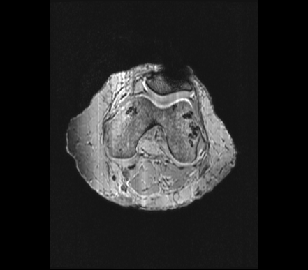
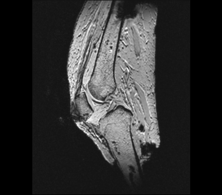
These settings were extracted from the DICOM header of a previous imaging session (CoBi Core project CBC_0049/01/dat/MRI/knee1?). This protocol has been used to create an isotropic, T1-weighted image set that reasonably represented the structures of interest, namely cartilage, soft-tissue and an outline of the bony anatomy.
EXAMPLE IMAGES
Axial:
Sagittal:
Coronal:

SEQUENCE 2: DESS-APPROX
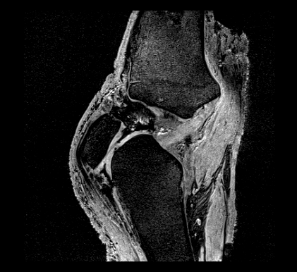
The goal of this imaging protocol is to acquire a sagittal plane image set with an in-plane resolution less than 0.5 mm, an out-of-plane resolution less than 1.5 mm and a large enough field of view inclusive of both tibiofemoral and patellofemoral cartilage. This image set will likely be utilized for geometric reconstruction of cartilage. It may also support geometric reconstruction of menisci.
Contrast Type: Double-Echo Steady-State (DESS), T1-weighted
Scanning Sequence: Gradient Echo (GR)
Sequence Variant: SP\OSP
Scan Options: SAT1\WE
Acquisition Type: 3D
Slice Orientation: sagittal
Resolution (in-plane): 0.36 x 0.36 mm (sagittal)
Slice Thickness: 0.70 mm
Repetition time (TR): 16.3 ms?
Echo time (TE): 4.78 ms?
Number of Averages: 1
Imaging Frequency: 123.25643
Flip angle: 25 degrees
Field of View: 140.0 x 140.0 mm (384 x 384 pixels)
Scan Time: 15.28 minutes?
EXAMPLE IMAGE
Sagittal:
SEQUENCE 3: MESE-APPROX
The goal of this imaging protocol is to acquire an axial plane image set with an in-plane resolution less than 0.5 mm, an out-of-plane resolution less than 1.5 mm and a large enough field of view inclusive of collateral and cruciate ligaments, quadriceps tendon and patellar ligament. This image set will likely be utilized for geometric reconstruction of ligaments. It may also support geometric reconstruction of menisci.
Imaging Trial 5: March 20, 2014
Proposed scans
- Obtain a 3D T1-weighted image set with fat suppression.
- Protocol: t1_fl3d_sag_p2_iso_0.4_fs
- Plane: 3D
- Desired resolution: 0.3409 x 0.3409 x 0.7 mm
- Protocol: t1_fl3d_sag_p2_iso_0.4_fs
- Obtain multi-plane MESE type images:
- Protocol: pd_tse_cor_p2_384
- Plane 1: Sagittal
- Desired resolution: 0.3409 x 0.3409 x 3.0 mm thickness (no gap)
- Protocol: pd_tse_cor_p2_384
- Plane 2: Axial
- Desired resolution: 0.3409 x 0.3409 x 3.0 mm thickness (no gap)
- Protocol: pd_tse_cor_p2_384
- Plane 3: Coronal
- Desired resolution: 0.3409 x 0.3409 x 3.0 mm thickness (no gap)
- Protocol: pd_tse_cor_p2_384
- Obtain multiple MESE type images with different # of excitations and thickness:
- Protocol: pd_tse_cor_p2_384
- Plane: Sagittal
- Desired resolution: 0.3409 x 0.3409 x 1.0 mm thickness (2 mm gap)
- # of excitations: 1
- Protocol: pd_tse_cor_p2_384
- Plane: Sagittal
- Desired resolution: 0.3409 x 0.3409 x 1.0 mm thickness (2 mm gap)
- # of excitations: 3
- Protocol: pd_tse_cor_p2_384
Results
-- aerdemir 2014-06-03 00:33:10 A detailed documentation of imaging parameters of protocols from this trial and from previous trials can be found in CFknee.protocol.xls - information provided by Shannon Donola (Case Imaging Center @ University Hospitals).
-- aerdemir 2014-03-23 13:25:18 Scan numbers are based on the order of the imaging as implemented in MRI session. Scans 1 & 2 were localizers.
SCAN 3
Protocol name. pd_tse_axial_p2_384
Goal. An axial plane MESE-type scan with approximately 0.35 mm x 0.35 mm x 3 mm (slice thickness)

SCAN 4
Protocol name. pd_tse_sag_p2_384
Goal. A sagittal plane MESE-type scan with approximately 0.35 mm x 0.35 mm x 3 mm (slice thickness)

SCAN 5
Protocol name. pd_tse_cor_p2_384
Goal. A coronal plane MESE-type scan with approximately 0.35 mm x 0.35 mm x 3 mm (slice thickness)

SCAN 6
Protocol name. pd_tse_sag_1.4mmslice_1avg
Goal. A sagittal plane MESE-type scan with approximately 0.35 mm x 0.35 mm x 1.4 mm (slice thickness) + 1.4 mm (gap); number of excitation = 1 (slice thickness is a limiting factor)

SCAN 7
Protocol name. pd_tse_sag_1.4mmslice_3avg
Goal. A sagittal plane MESE-type scan with approximately 0.35 mm x 0.35 mm x 1.4 mm (slice thickness) + 1.4 mm (gap); number of excitation = 3

SCAN 8
Protocol name. t1_fl3d_sag_350x350x700_fs
Goal. A 3D T1-weighted image set with fat supression with higher resolution in sagittal plane, approximately 0.35 mm x 0.35 mm x 0.7 mm

SCAN 9
Protocol name. t1_fl3d_sag_350x350x700
Goal. A 3D T1-weighted image set without fat supression with higher resolution in sagittal plane, approximately 0.35 mm x 0.35 mm x 0.7 mm

Imaging Trial 4: March 4, 2014
-- hallorj 2014-03-04 15:59:15 add exact protocol names, provided by the UH imaging resource, from the DICOM headers for each sequence below. This should facilitate use of the correct sequence during the imaging sessions.
Attendees: Chris, Shannon (UH); Ahmet, Craig, Snehal (CC)
The goal of this imaging trial was to conduct a full mock-up imaging of a knee specimen including:
2 T1-weighted, isotropic (0.5mm) images (based on CoBi Core's previous protocols)
- with fat suppression (= WE = Water Excitation)
- without fat suppression (t1_fl3d_sag_p2_iso_0.5)
- 2 DESS-type, sagittal plane images (~0.3x0.3x0.7):
- DESS-APPROX sequence (based on the settings from Nov. 14, 2013)
- T2 spin echo (suggested by Chris to replicate OAI DESS image contrast).
- 3 MESE-type, axial plane image sets: (slice thickness = 3mm)
- MESE (OAI protocols)
- Turbo Spin Echo (TSE) (to replicate OAI MESE image contrast).
Results
DICOM ORDER #4) T1-ISO WITHOUT FAT SUPPRESION:
Series Description: t1_fl3d_sag_p2_iso_0.4_we
Resolution: 0.5 x 0.5 x 0.5 mm


Notes from Imaging Session
This imaging sequence corresponded to Scan 3 of the whole protocol as it was setup in the MRI machine. It was intended to be a T1-weighted isotropic imaging (flash 3D without fat suppression) with 0.5 mm x 0.5 mm x 0.5 mm voxel size. The femur was placed through the bore first (head first). Images are misoriented as it was assumed that the tibia was placed through the bore first during direction setup (feet first). In future imaging sessions, the team needs to ensure that femur goes first and inform the imaging personnel so that appropriate orientation is set up.
Sequence name: t1_fl3d_sag_p2_iso_0.4_we FOV (mm): 240 mm read x 65.8% --> 158 x 158 x 240 TR (ms): 20 TE (ms): 6.01 # of slices: 320 Flip angle (deg.): 25 Bandwidth (Hz/pixel): 210 Chemical Shift (pixels): No. excitations averaged: 1 ETL: 1 Phase encode axis: A/P Distance factor (%): 0 (irrelevant for 3D) Phase oversampling: 0 Slice oversampling: 0 Phase/slice/read resolution: 500 um (?) Slice partial Fourier: 7/8 Phase partial Fourier: 1 (?) Readout partial Fourier: 1 (?) X-resolution (mm): 0.5 Scan time (min.): ~21
DICOM ORDER #5) T1-ISO WITH FAT SUPPRESION:
Series Description: t1_fl3d_sag_p2_iso_0.4_fs
Resolution: 0.5 x 0.5 x 0.5 mm


Notes from Imaging Session
This imaging sequence corresponded to Scan 4 of the whole protocol as it was setup in the MRI machine. It was intended to be a T1-weighted isotropic imaging (flash 3D with fat suppression) with 0.5 mm x 0.5 mm x 0.5 mm voxel size. All imaging settings are essentially the same as those of without fat suppression (see immediately above).
Sequence name: t1_fl3d_sag_p2_iso_0.4_fs
DICOM ORDER #6) DESS-TYPE (BASED ON OAI):
DESS-APPROX_HEADER_03.04.14.txt
Series Description: dess_3dsag_we
Resolution: 0.3409 x 0.3409 x 0.7 mm

Notes from Imaging Session
This imaging sequence corresponded to Scan 5 of the whole protocol as it was setup in the MRI machine. It was intended to reproduce DESS imaging protocol from the OAI study. The goal was to obtain a sagittal image set with ~0.35 mm x ~0.35 mm in plane resolution and 0.7 mm image thickness (no gap). Note that this is NOT T2 spin echo, it is as close as it gets to OAI. A T2 spin echo may be brighter in the cartilage.
Sequence name: dess_3dsag_we FS: Yes (-- aerdemir 2014-03-10 12:02:30 I assume WE.) Plane: Sagittal FOV (mm): 240 mm read (H/F) x 62.5% (A/P) --> 240 mm x 150 mm x 150 mm Slice thickness/gap (mm/mm): 0.7/0 TR (ms): 16.5 TE (ms): 5 # of slices: 160 Flip angle (deg.): 25 Bandwidth (Hz/pixel): 187 Chemical Shift (pixels): No. excitations averaged: 1 ETL: 1 Phase encode axis: Distance factor (%): 0 Phase oversampling: 0 Slice oversampling: 20% Phase/slice/read resolution: Slice partial Fourier: 6/8 Phase partial Fourier: Readout partial Fourier: X-resolution (mm): 240/704 --> 0.3409 Y-resolution (mm): 150/352 --> 0.4261 (-- aerdemir 2014-03-10 12:02:30 I took a note of '150/352'. I am not sure what it corresponds to.) Scan time (min.): ~14
DICOM ORDER #7) T1 VIBE (DESS-LIKE CONTRAST AND RESOLUTION):
DESS-type_T1_vibe_HEADER_03.04.14.txt
Series Description: T1_vibe_we_sag_iso_p2_EP
Resolution: 0.3409 x 0.3409 x 0.7 mm

Notes from Imaging Session
This imaging sequence corresponded to Scan 6 of the whole protocol as it was setup in the MRI machine. It was intended to be a sagittal image set with ~0.35 mm x ~0.35 mm in plane resolution and 0.7 mm image thickness (no gap). Note that this imaging sequence has been previously referred by the team as DESS-APPROX (see sequence 2 of November 14, 2013 trial). It is actually closer to a T1-weighted imaging sequence with fat supression and can be used to replace DESS-type imaging for cartilage reconstruction.
Sequence name: t1_vibe_we_sag_isop2_EP Plane: Sagittal FOV (mm): 240 mm x 62.5% --> 240 mm x 150 mm x 150 mm Slice thickness/gap (mm/mm): 0.7/0 TR (ms): 12 TE (ms): 6.2 # of slices: 240 Flip angle (deg.): 25 Bandwidth (Hz/pixel): 190 Chemical Shift (pixels): No. excitations averaged: 1 ETL: Phase encode axis: Distance factor (%): 0 Phase oversampling: 0 Slice oversampling: 0 Phase/slice/read resolution: Slice partial Fourier: 6/8 Phase partial Fourier: Readout partial Fourier: X-resolution (mm): 240/704 --> 0.3409 Scan time (min.): ~11.5
DICOM ORDER #8) MESE-TYPE TSE 2D, SAGITTAL (BASED ON OAI):
MESE-type_TSE_2D_SAG_HEADER_03.04.14.txt
Series Description: pd_tse_cor_p2_384
Sequence Name: *tse2d1_14
Resolution: 0.3409 x 0.3409 x 3.0 mm

Notes from Imaging Session
This imaging sequence corresponded to Scan 7 of the whole protocol as it was setup in the MRI machine. It was intended to reproduce MESE imaging protocol from the OAI study. The goal was to obtain a sagittal image set with ~0.35 mm x ~0.35 mm in plane resolution and 3 mm image thickness (no gap).
Sequence name: pd_tse_cor_p2_384 Plane: Sagittal FOV (mm): 240 x 62.5% --> 240 x 150 x 150 Slice thickness/gap (mm/mm): 3/0 TR (ms): 8000 TE (ms): 11 # of slices: 35 Flip angle (deg.): 90 Bandwidth (Hz/pixel): 222 Chemical Shift (pixels): No. excitations averaged: 1 ETL: 14 Phase encode axis: Distance factor (%): 0 Phase oversampling: 0 Slice oversampling: 0 Phase/slice/read resolution: Slice partial Fourier: Phase partial Fourier: Readout partial Fourier: X-resolution (mm): 240/704 --> 0.3409 Scan time (min.): ~4
DICOM ORDER #9) MESE-TYPE TSE 2D, AXIAL:
MESE-type_TSE_2D_AXL_HEADER_03.04.14.txt
Series Description: pd_tse_cor_p2_384
Sequence Name: *tse2d1_14
Resolution: 0.3516 x 0.3516 x 3.0 mm

Notes from Imaging Session
This imaging sequence corresponded to Scan 8 of the whole protocol as it was setup in the MRI machine. It was intended to be an axial image set with ~0.35 mm x ~0.35 mm in plane resolution and 3 mm image thickness (no gap).
Sequence name: pd_tse_cor_p2_384 Plane: Axial FOV (mm): 180 x 75% --> 180 x 135 x 135 Slice thickness/gap (mm/mm): 3/0 TR (ms): 13000 TE (ms): 10 # of slices: 70 Flip angle (deg.): 90 Bandwidth (Hz/pixel): 222 Chemical Shift (pixels): No. excitations averaged: 1 ETL: 14 Phase encode axis: Distance factor (%): 0 Phase oversampling: Slice oversampling: 0 Phase/slice/read resolution: Slice partial Fourier: Phase partial Fourier: Readout partial Fourier: X-resolution (mm): 180/512 --> 0.3516 Scan time (min.): ~5.7
DICOM ORDER #10) MESE-TYPE TSE 2D, AXIAL (STACKED THIN SLICES):
MESE-type_TSE_3D_AXL_HEADER_03.04.14.txt
Series Description: pd_tse_cor_p2_384
Sequence Name: *tse3d1_14
Resolution: 0.3516 x 0.3516 x 0.7 mm

Notes from Imaging Session
This imaging sequence corresponded to Scan 9 of the whole protocol as it was setup in the MRI machine. It was intended to be a It was intended to be a stacked set of axial image acquisitions with ~0.35 mm x ~0.35 mm in plane resolution and 0.7 mm image thickness (no gap).
Sequence name: pd_tse_cor_p2_384 Plane: Axial FOV (mm): 180 x 75% --> 180 x 135 x 135 Slice thickness/gap (mm/mm): 0.7/0 TR (ms): 1390 TE (ms): 14 # of slices: 36 (x 7) Flip angle (deg.): 90 Bandwidth (Hz/pixel): 222 Chemical Shift (pixels): No. excitations averaged: 1 ETL: 14 Phase encode axis: Distance factor (%): 0 Phase oversampling: Slice oversampling: 0 Phase/slice/read resolution: Slice partial Fourier: Phase partial Fourier: Readout partial Fourier: X-resolution (mm): 180/512 --> 0.3516 Scan time (min.): ~23 min
Discussion
-- aerdemir 2014-03-10 12:26:15 Based on the results above, should our specimen imaging trial include
- T1-ISO WITHOUT FAT SUPPRESSION: (0.5 mm x 0.5 mm x 0.5 mm) for overall imaging of the knee including registration markers.
- T1 VIBE (DESS-LIKE CONTRAST AND RESOLUTION): (0.341 mm x 0.341 mm x 0.7 mm slice thickness no gap: sagittal plane) for reconstruction of bone and cartilage. This may be helpful to reconstruct cruciate ligaments and menisci.
- MESE-TYPE TSE 2D: (0.341 mm x 0.341 mm x 2 mm slice thickness no gap (or 1mm slice thickness with 2 mm gap) - multi plane: sagittal, coronal, and axial) for reconstruction of ligaments, tendons, and menisci. We may need to run another test trial to see if we can acquire such scans with a desirable FOV and contrast.
Imaging Trial 3: February 17, 2014
Attendees: Chris, Shannon (UH); Ahmet, Craig, Snehal (CC)
The goal of this imaging trial was to conduct a full mock-up imaging of a knee specimen including:
an isotropic T1 weighted imaging (based on CoBi Core's previous protocols),
- a sagittal plane DESS imaging (based on OAI protocols), and
- an axial plane MESE imaging (based on OAI protocols).
In addition, alignment of the image sets in the MR coordinate system was elaborated upon.
Remarks during Session (Ahmet)
- The center image location will be provided. This information may not be correct in DICOM files.
- Support to fill-in the settings table, as in OAI manuscript, need to be provided.
- Oblique imaging will be conducted so that image sets become orthogonal.
- Sequence name and settings will be provided.
- Attempted imaging
- T1; 0.4 mm x 0.4 mm x 0.4 mm (resolution); 230 mm x 160 mm x 160 mm (fov)
- Contrast is anticipated to look like SEQUENCE 1: T1-ISO (see above).
- DESE (sagittal plane); 0.35 mm x 0.35 mm x 0.7 mm (resolution); 135 mm x 135 mm x 112 mm (fov)
Contrast is anticipated to look like this (Figure 4 of OAI protocols). Also see SEQUENCE 2: DESS-APPROX (see above).
- MESE (axial plane); 0.30 mm x 0.30 mm x 2.0 mm (resolution); 120 mm x 120 mm x 180 mm (fov); 3 different T2 settings
Contrast is anticipated to look like this (Figure 8 of OAI protocols, note that OAI protocols are sagittal).
- Thickness and fov are at the bound of the capabilities of the imaging system.
- Scan times are long, ~36 min.
- T1; 0.4 mm x 0.4 mm x 0.4 mm (resolution); 230 mm x 160 mm x 160 mm (fov)
- For larger knees out of plane resolution may need to be increased to accommodate increased fov requirement. This can also be compensated by additional scan time while trying to keep desirable resolution.
- Images of higher resolution can be filtered. Number of excitations can be increased at the cost of scan time.
Remarks from UH (Shannon)
Image sequences of mock-up trial of February 17, 2014:
- Fast 3Plane Loc (this is our rough scan to just get an idea of the location of the leg in each plane)
- voxel size: 2.3*2.3*5.0mm
- slice thickness: 0.5mm
- 1 slice, every different plane
- Arc T1 axial (actually sagittal)
- voxel size: 1.2*1.2*1.6mm
- slice thickness: 1.6mm
- 50 slices
- t1_F13d_sag_P2_iso_0.4_we
- voxel size: 0.4 * 0.4 * 0.4mm
- slice thickness: 0.40mm
- position: L5.1, A 37.0, H10.2
- 320 slices/slab (1 slab)
- dess_3dsag_we
- voxel size: 0.4*0.4*0.7mm
- slice thickness: 0.70mm
- position: L5.1, A34.8, H21.3
- 160 slices/slab (1 slab)
- tse_te20-40-60_300um (this is your MSME)
- voxel size: 0.3*0.3*2mm
- slice thickness: 2mm
- position: L1.5, A38.5, H11.5
- 90 slices
Results
Scan 3: T1-ISO
Axial:

Sagittal:

Coronal:

Scan 4: DESS
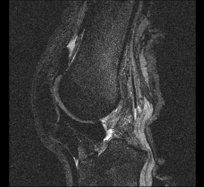
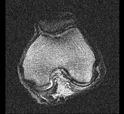
Scan 5: MESE
Imaging Trial 2: January 29, 2014
Imaging Trial 1: November 14, 2013
-- hallorj 2013-11-05 15:11:02 An imaging test session is setup for November 14, 2013 from 1-2:30 pm. Myself and/or Snehal will attend. The BioRobotics Core can provide a knee specimen. If the specimen is currently a whole leg, we'll need to prepare it for imaging. Thawing will have to occur the day before. During the test session, we will look at the metal artifact issue (bring the brass mounting plugs) and image acquisition settings will be tested. I envision starting from the T1 weighted settings we currently use and adding one of the above T2 acquisitions. The T2 set should focus on cartilage while the T1 should be good for the other soft-tissues (ligaments, tendon, meniscus). An email will be sent to Dr. Carl Winalski (a radiologist and member of the advisory board) for feedback on the settings.
Results from imaging testing session conducted on November 14, 2013.
Machine: Siemens MAGNETOM Skyra 3T, Clinical
Receiver Coil: knee coil
Scan 4 (Sequence 1):
- T2 proton density.
DICOM header: t2_protondensity.txt

Scan 5 (Sequence 2): DESS-APPROX
- 3D dual-echo in steady state (DESS), first approximation of OAI DESS protocol
Reference: http://www.ncbi.nlm.nih.gov/pubmed/18786841
DICOM header: DESS_approx_sag_HEADER.txt

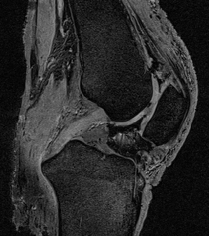
- Coronal and sagittal image samples showing articular cartilage and PCL respectively
Scan 7 (Sequence 3): BRASS ARTIFACTS
- Evaluation of image artefacts caused by brass components of marker fixture.
- Marker components and a piece of delrin were taped to a piece of paper and placed on the MRI phantom.
- Bottom right shadow in the image below is resulted from a piece of delrin. Rest of the artefacts are due to brass components.
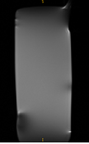
Hargreaves, Brian A, Pauline W Worters, Kim Butts Pauly, John M Pauly, Kevin M Koch, and Garry E Gold. “Metal-induced artifacts in MRI.” AJR. American journal of roentgenology 197, no. 3 (September 2011): 547–555. doi:10.2214/AJR.11.7364. http://www.ncbi.nlm.nih.gov/pubmed/21862795
-- aerdemir 2014-02-24 12:19:34 For each imaging sequence, provide a sample image and the DICOM header as a text file.