-- aerdemir 2016-04-14 17:10:18 This specification is asking for input from the community. Please provide your feedback
by editing the /Discussion page, or
by responding to relevant forum entry, or
by sending an e-mail to Ahmet Erdemir, <erdemira@ccf.org>.
Contents
Target Outcome
This specification targets at volumetric reconstruction of a tissue of interest, specifically the definition of the boundaries of the tissue,
- as an image volume, and
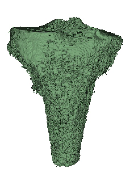
- as a surface representation.
Prerequisites
Infrastructure
ITK-SNAP. ITK-SNAP is a software application used to segment structures in 3D medical images (GPL license, see http://www.itksnap.org).
Slicer. Slicer is a free, open source software package for visualization and image analysis (BSD-style open source license, see http://www.slicer.org).
MITK. The Medical Imaging Interaction Toolkit (MITK) is a free open source software platform aimed at providing support for an efficient software-development of methods and applications dealing with medical images (BSD-style license, see http://www.mitk.org).
SimpleITK. SimpleITK is a simplified layer built on top of ITK to facilitate its use in rapid prototyping of image analysis that can be used in interpreted languages, e.g. Python, (Apache 2.0 License license, see http://www.simpleitk.org/).
Convert3D. C3D is a command-line tool for converting 3D images between common file formats, which also includes a growing list of commands for image manipulation, such as thresholding and resampling (GPL license, see http://www.itksnap.org/pmwiki/pmwiki.php?n=Downloads.C3D).
Previous Protocols
For more details, see Specifications/ExperimentationAnatomicalImaging.
Protocols
Input
Set(s) of MRI in NifTI format
Overview
- Download desired image volume for the desired specimen (NifTI, .nii).
- Load the desired image volume into Slicer.
- Segment the tissue of interest using the detailed tissue specific segmentation procedures described below.
- NOTES:
- Save the segmented label map regularly to avoid losing tedious work through program crashes.
- Segmented volume can be overlayed on other image sets to evaluate boundaries, however it can only be further edited when overlayed on MRIs with the same size/resolution as the MRI from which it was originally created.
- After completion of the segmentation, the volume should be exported as an image volume (NIFTI)
4. Generate a triangulated surface from all segmented tissues (without smoothing, this is considered a RAW STL) in STL format.
- NOTE: Complete this step only after all tissue segmentations are completed, as it is common to make changes throughout the process.
Image/Data Input Procedures
Load MRI data:
- NifTI:
File -> Add Data (or click Data icon button)
- Click "Choose File(s) to add" button.
- Select desired MRI(s) (.nii)
- Click "Open".
- DICOM:
File -> DICOM (or click DCM icon button).
- Click "Import" button.
- Select directory containing DICOM image slices (.IMA).
- Click 'Add link'.
- CLick 'OK' after images load.
- Select desired Series in DICOM Browser window.
- Click 'Load'.
Load segmented label map image data (NifTI):
File -> Add Data (or click Data icon button).
- Click 'Choose File(s) to Add'.
- Select Segmented label map image(s) (NifTI, .nii).
- Click 'Open'.
- Select 'Show Options'.
Select 'LabelMap' for all label map volumes.
- Click 'Ok'.
Importing a segmented label map to the "segment editor" module
* Load segmented label map image as described above. * From the “Modules” drop-down menu, select “Segment Editor”
- Check that the Master Volume is set as the desired MRI to be segmented.
- Load the label maps into the segment editor:
- click “Segmentations”
- scroll down and expand the “Export/Import models and label maps” tab
- For “Operation”, select “Import”
- Choose the desired label map from the “Input node” drop down.
- Click “Import”
Image/Data Output Procedures
Save segmented label map (as NifTI):
File -> Save, or Save icon
- Deselect all modified/selected files in the 'File Name' field
- Select/Check the desired segmented label map volume (default type: NRRD, .nrrd)
- Set the 'File Format' to NifTI (.nii)
Rename the label map volume as desired, see naming convention: Specifications/DataManagement
- Click 'Save'
Save triangulated surface, STL (a.k.a. Slicer Model):
File -> Save, or Save icon
- Deselect all modified/selected files in the 'File Name' field
- Select/Check the desired triangulated surface (default type: VTK, .vtk)
- Set the 'File Format' to STL (.stl)
Rename the triangulated surface as desired, see naming convention: Specifications/DataManagement
- Click 'Save'
Exporting a label map from the "segment editor" module:
- If you are in the editing mode, click “Segmentations”
- Hide all segmentations besides the one that you wish to export using the eye toggle.
- Scroll down and expand the “Export/Import models and label maps” tab. For “Operation”, select “Export”
- From the “Output node” drop down, select the desired name. Note that this will override the existing label map with that name. If you wish, you may select “export to new labelmap” and then rename it as desired when saving.
- Expand the “Advanced” tab, and under “Exported Segments” drop down, select “Visible”.
- Click “Export”
- Save the label map using the directions above
Viewing Options
Under the pin drop-down menu (under >> button) in any of the 2D slicer viewers:
- Link viewers to ensure that they all display the same label map volumes.
- Two label maps can be overlayed on the MRI in order to compare segmented boundaries between two different structures. The label map you want to edit should be set as the Label Layer (icon in pin drop-down 2D viewer menu with an "L"). The other label map can be loaded as the Foreground Layer (icon with an "F").
- Change transparency of the label map in 2D viewers by changing the percent opacity by changing value near the eye (display/hide) icon: 0.0 (transparent) to 1.0 (opaque).
- Change contrast/brightness of MRI using the default mouse cursor pointer tool by clicking and dragging up/down and left/right in any of the 2D viewers.
Segmentation Procedures
Segmentation Setup
- From the "Modules" drop-down menu, select "Editor"
- When multiple MRI sets are loaded, in most cases the desired MRI to be segmented should be the same as the Master Volume. It is also possible to do segmentation on a different MRI than the Master Volume. For example, different MRIs can be displayed in different windows, e.g. those that are ligament specific and cartilage specific. When linked, Slicer uses interpolation for coupled viewing of the image sets that are already spatially aligned. For segmentation, one can use one image set as the master volume but segment in the other allowing high resolution segmentation volume from images with lower resolution.
If it is the first time entering Editor Module, click Apply to select the default GenericAnatomyColors to create a new Merge Volume (i.e. label map, with the same size/resolution as the Master Volume)
- If not the first time, make sure the desired label map overlayed (i.e. being edited) in the 2D slice viewers is the same as the Merge Volume.
Manual Segmentation
For first time users, see
https://www.slicer.org/wiki/Documentation/4.8/Modules/Editor for more information.
- Perform 'Segmentation Setup'.
- Highlight the anatomy of interest in every slice, in each image plane orientation as appropriate (coronal, sagittal, axial).
- Different tools are available to highlight anatomy of interest a desired label (e.g. label1):
- Use the Paint Effect (under 'Edit Selected Label Map' tab, top row of icons, 3rd icon from left) [with an appropriate/largest radius] to fill in the area using a brush.
- Use the Draw Effect (under 'Edit Selected Label Map' tab, top row of icons, 4th icon from left) to draw the boundaries of the area - freehand or by right mouse click to set the polygon corners and left click to fill in the polygon.
- Use the eraser (under 'Edit Selected Label Map' tab, top row of icons, 2nd icon from left) to change the behaviour of the tool, e.g. brush or pencil, to erase rather than draw.
- Tips and Shortcuts using 3DSlicer:
- In Editor Mode:
- 'c' to open list of labels, type # of label id and enter to switch labels quickly
- 'z' to undo
- 'y' to redo
- 'd' for Draw Effect
- 'p' for Paint Effect
- 'e' to erase from label
- arrow keys to move forward/background a slice
- In Editor Mode:
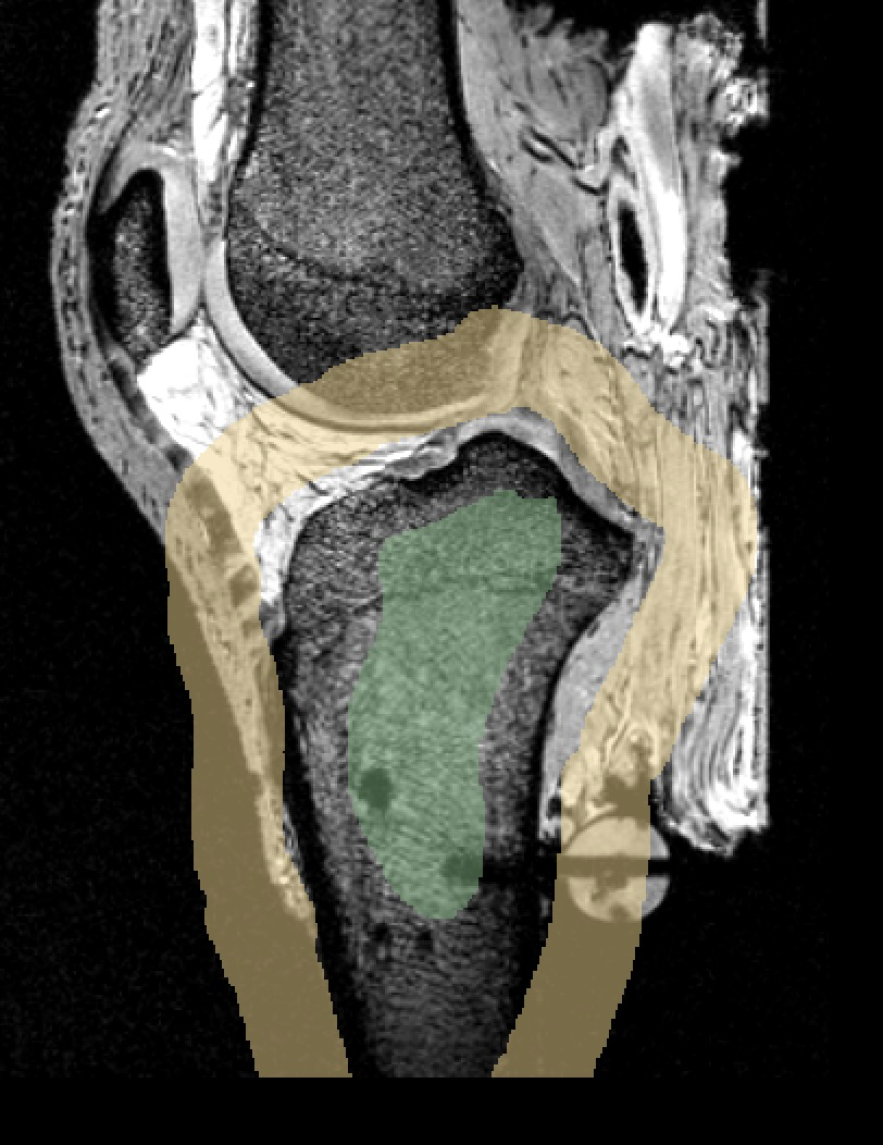
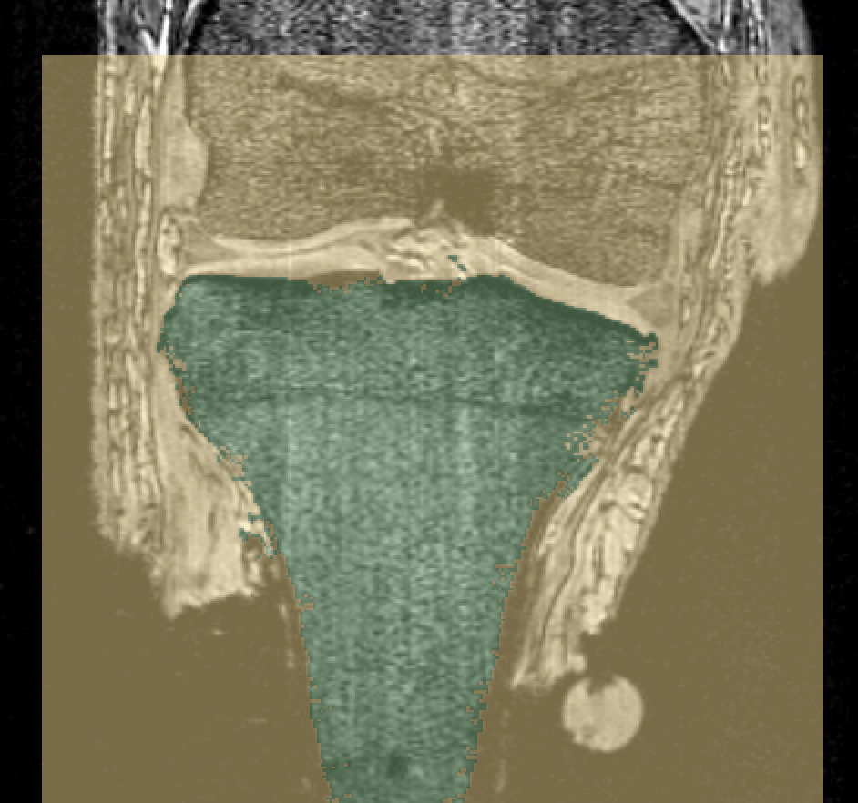
Grow-Cut Segmentation
- Perform 'Segmentation Setup'
- Perform the following steps on roughly equally-spaced slices in each image plane orientation as appropriate (coronal, sagittal, axial).
- Use the Paint Effect (under 'Edit Selected Label Map' tab, top row of icons, 3rd icon from left) [with an appropriate/largest radius] to highlight anatomy of interest (foreground) using a specific label (e.g. label1).
- Use the Paint Effect to highlight area around anatomy of interest (background) with a different label (e.g. label2).
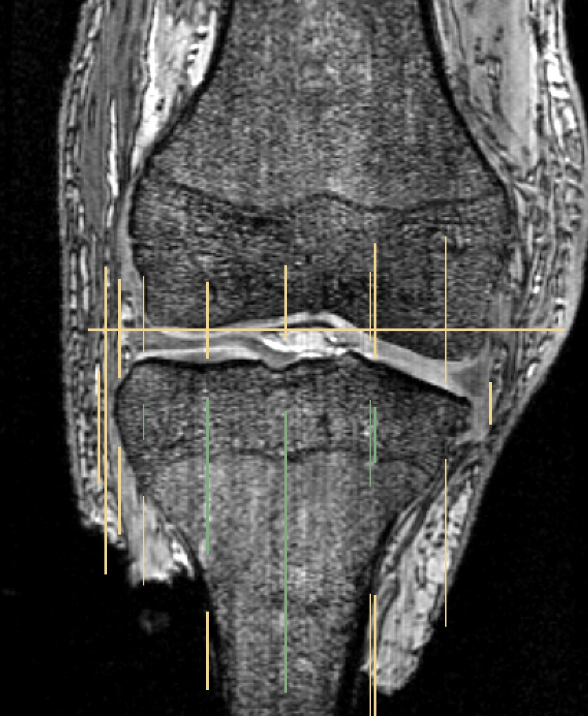
- Use the Paint Effect to "cap" boundaries of anatomy of interest (background) to prevent foreground leakage (before/after anatomy of interest appears).
Select GrowCutEffect icon (under 'Edit Selected Label Map' tab, bottom row of icons, 3rd icon from left).
- Click the "Apply" button (Slicer window graphics will freeze until the grow cut algorithm is complete).
- Remove the background label:
Select ChangeLabelEffect (under 'Edit Selected Label Map' tab, bottom row of icons, 3rd icon from right).
- Select label2 as input and background [0] as output.
- Click the "Apply" button.
See figures below for example of segmentation using GrowCutEffect with foreground (green) and background (yellow).
For more information on Growth Cut Effect refer to the 3DSlicerWiki http://www.slicer.org/slicerWiki/index.php/Modules:GrowCutSegmentation-Documentation-3.6.
Image Processing Procedures
Label Map Smoothing
From the Modules drop-down menu, select 'Surface Models' -> 'Label Map Smoothing'
- Set Gaussian Smoothing Parameters, Sigma based on image resolution (e.g. 0.7 for cartilage MRI, resolution = 0.35 x 0.35 x 0.7 mm)
- From 'Input Volume' drop-down menu, select desired label map
- From 'Output Volume' drop-down menu, select 'Create and rename new Volume'
- Enter new name as desired, click 'OK'
- Click Apply
Joint Smoothing
Joint smoothing is performed in the “Segment Editor” module
- Import the desired label map to the segment editor as described above in input procedures.
- Select one of the label maps in the list, Click “Edit Selected”
- Ensure that only the label maps you wish to perform joint smoothing on are visible. Hide all others using the eye toggle.
- Under “Effects” click “Smoothing”.
- In the “smoothing method” drop down select “Joint Smoothing”.
- Set the desired smoothing factor: try the default, and if it causes the label map to shrink too much, press undo, and repeat with a lower smoothing factor.
- Click “Apply”
- Check the results, and perform touch ups as needed using the tools in "Effects".
- Once you are satisfied with the results, you must export the label maps from the segment editor module before saving. See output procedures for details.
Generate Triangulated Surface (STL) from Label Map
Note: : In this stage a RAW STL is being created, therefore no smoothing procedures will be performed when generating the STL.
From the Modules drop-down menu, select 'Surface Models' -> 'Model Maker'
- Under 'IO' tab, from 'Input Volume' drop-down menu, select desired Label Map
- In Model drop-down menu, either 'Create and rename new Hierarchy' (e.g. default 'Models'), or select an existing Model Hierarchy.
- NOTE: all models can be generated under the same or separate model hierarchies
- Under 'Create Model' tab, specify a desired 'Model Name' for the select Label Map.
- FOR RAW STL:
- Under 'Model Maker Parameters', set 'Smooth' to zero.
- Under 'Model Maker Parameters', set 'Decimate' to zero.
- Click Apply button.
- From Editor:
Select the MakeModelEffect
- Set desired Label Map as the Merge Volume
- If no smoothing is desired, deselect 'smooth model'
- Click Apply button.
- From Segment Editor:
- If you are in the editing mode, click “Segmentations”
- Hide all segmentations besides the one that you wish to export.
- Scroll down and expand the “Export/Import models and label maps” tab. For “Operation”, select “Export”. For the “Output type” select “Models”.
- From the “Output node” drop down, select the desired model hierarchy
- NOTE: all models can be generated under the same or separate model hierarchies
- Expand the “Advanced” tab, and under “Exported Segments” drop down, select “Visible”.
- Click “Export”
- Save the STL
Tissue-Specific Procedures
Below are the guidelines for segmentation procedures based on tissue type.
Registration Markers
INPUT: general purpose MRI
Procedure for registration marker segmentation:
- Use level tracing effect (foreground label) to segment registration markers on various slices, in various orthogonal viewing planes.
- On slices which were segmented in the prior step, manually define the area surrounding the markers with a different color (background label)
- Apply the Grow Cut effect automatically segment the remaining regions of the registration marker (as described above).
Remove the background label using the ChangeLabelEffect (as described in the Grow Cut procedure).
- FOR SPHERICAL FEMUR/TIBIA MARKERS:
- Manually segment to fill in the screw hole on spherical registration markers on femur and tibia.
- IF MARKERS ARE PLASTIC SPHERES WITH ULTRASOUND GEL:
- Manually segment to fill in bubbles using 'art' to define outer spherical boundary.
LABELS: FMR-M, FMR-L, FMR-P, TBR-M, TBR-L, TBR-P, PTR-S, PTR-M, PTR-L (includes bone and relative marker location, e.g. FMR-M is comprised of FM for femur, R for registration marker, and -M for medial).
oks001, femur and tibia registration markers (posterior):
Bones
INPUT: cartilage MRI (sagittal)
Procedure for bone segmentation:
- Perform Grow Cut segmentation procedure on desired bone
- Perform Label Map Smoothing to remove Grow Cut boundary noise
- Perform manual segmentation to more accurately define bone boundary
- Iteratively repeat last two steps until boundary is as desired
NOTE: Cortical bone will appear black in MR images, so outer edge of black cortical region defines the bone surface.
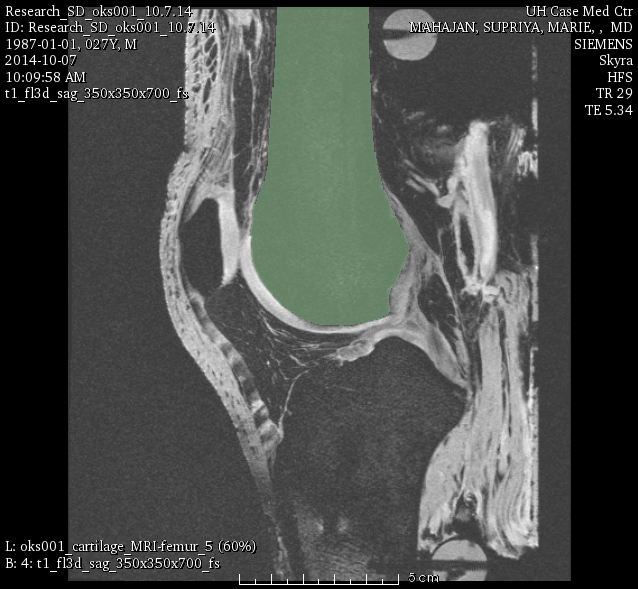
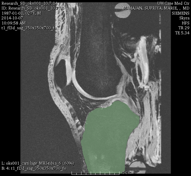
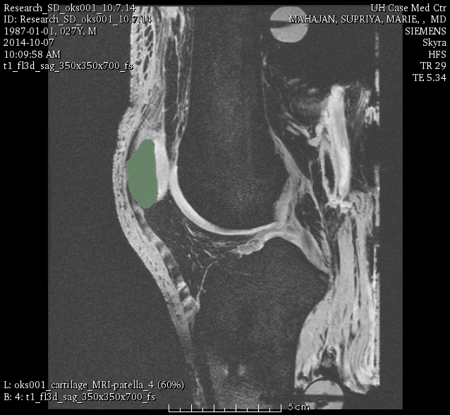
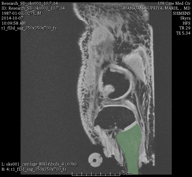
LABELS: FMB (femur), TBB (tibia), FBB (fibula), PTB (patella).
oks001, femur:
oks001, tibia:
oks001, patella:
oks001, fibula:
Cartilage
INPUT: cartilage MRI
Procedure for cartilage segmentation:
- See procedure for bone segmentation
Cartilage segmentation should be informed by bone segmentation (i.e. use bone boundary to help define cartilage boundary).
LABELS: FMC (femoral), TBC-M (medial tibial), TBC-L (lateral tibial), PTC (patellar).
oks001, femur cartilage:
oks001, patella cartilage:
oks001, medial tibia cartilage:
oks001, lateral tibia cartilage:
Menisci
INPUT: cartilage MRI
Procedure for menisci segmentation:
- Manual segmentation
- Label map smoothing
- Manual touch-up
Menisci segmentation should be informed by cartilage segmentation (i.e. use cartilage boundary to help define meniscus boundary).
LABELS: MNS-M (medial), MNS-L (lateral).
oks001, medial meniscus:
oks001, lateral meniscus:
Connective Tissue - Ligaments & Tendons
Procedure for patellar ligament, quadriceps tendon, ACL, PCL (and any connective tissue when applicable):
- PHASE 1 (INPUT: ligament MRI):
- Load sagittal ligament MRI.
- Perform the Grow Cut segmentation procedure on desired tissue.
- Modify the label map boundary manually if desired.
- Load cartilage MRI.
- Overlay previous ligament MRI segmented label map (from PHASE 1) over the cartilage MRI (as Foreground Layer, NOTE: make sure to increase opacity, default is 0).
- Create new label map (Merge Volume) from cartilage MRI (set as Label Layer).
- Manually segment the tissue using the ligament MRI label map boundaries as a guide.
Alternatively, one can display the ligament specific MRIs and the cartilage specific MRI in different windows. When linked, Slicer uses interpolation for coupled viewing of the image sets that are already spatially aligned. In return, one can do the segmentation on interpolated ligament MRIs using the cartilage MRI as the master volume for segmentation. This allows high resolution segmentation volume from images with lower resolution directly.
Procedure for LCL, etc.:
- Manual segmentation
- Label map smoothing
- Manual touch-up
Connective tissue segmentation should be informed by bone segmentation (i.e. use bone boundary to help define connective tissue boundary).
LABELS: ACL, PCL, LCL, PTL, QAT.
oks001, patellar ligament:
oks001, quadriceps tendon:
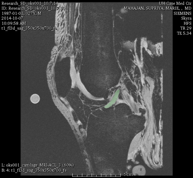
oks001, ACL:
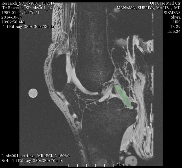
oks001, PCL:
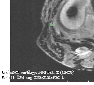
oks001, LCL:
Sample Results
3D SURFACE REPRESENTATION OF SEGMENTED REGIONS:
Output
- Volume of tissue of interest as a binary image aligned with original MRI coordinate system (raw, without filtering and smoothing)
- Surface representation of tissue of interest in STL format in MRI coordinate system (raw, without filtering and smoothing)
