Contents
Target Outcome
Finite element mesh of a tissue of interest ready for model development:
- node definitions
- element definitions
- node set definitions
- element set definitions
- surface set definitions
Prerequisites
Infrastructure
SALOME. SALOME is an open-source software that provides a generic platform for pre- (cad, meshing) and post-processing for numerical simulation (LGPL license, see http://www.salome-platform.org/).
FreeCAD. FreeCAD is an open-source three-dimensional computer aided design software (GPL and LGPL licenses, see http://www.freecadweb.org/).
MeshLab. MeshLab is an open-source, portable, and extensible system for the processing and editing of unstructured 3D triangular meshes (GPL license, see http://meshlab.sourceforge.net/).
OpenFlipper. OpenFlipper is an open-source, multi-platform application and programming framework designed for processing, modeling and rendering of geometric data (LGPL license, see http://www.openflipper.org/).
PyGTS. PyGTS is a Python binding for the GNU Triangulated Surface (GTS) Library to construct, manipulate, and perform computations on 3D triangulated surfaces, including boolean operations (GPL license, see http://pygts.sourceforge.net/).
pyFormex. pyFormex provides a wide range of operations on surface meshes, such as STLs; the software can also be used as a pre- and post-processor for Finite Element analysis programs (GPL license, see http://www.nongnu.org/pyformex).
IA-FEMesh. IA-FEMesh is freely available, interactive, structured hexahedral mesh generation software relying on surface projection method (BSD style license, see http://www.ccad.uiowa.edu/MIMX/projects/IA-FEMesh).
Blender. Blender is the free and open source 3D creation suite, which supports the entirety of the 3D pipeline, including: modeling, rigging, animation, simulation, rendering, compositing, motion tracking, video editing, and game creation. (GPL license, see https://www.blender.org/).
Previous Protocols
For more details, see Specifications/GeometryGeneration.
Protocols
Input
- Explicit surface representation of tissue of interest; in STL format in MRI coordinate system (processed with volume preserving smoothing)
Parametric surface representation of tissue of interest in IGES & STP format in MRI coordinate system (processed with volume preserving smoothing)
Parametric solid model of tissue of interest in IGES & STP format in MRI coordinate system (processed with volume preserving smoothing)
Procedures
-- aerdemir 2013-12-30 15:14:36 This section may list general purpose procedures and alternatives to utilize the same input to reach the same output. Procedures optimized for specific tissues should also be provided in here.
TETRAHEDRAL MESHING
When starting with explicit surface representation
Manual
- Import surface into mesh module of SALOME. (note that surface mesh density will be dictated by the imported surface)
- Define mesh generation parameters, e.g. NETGEN 3D Parameters. (this will dictate internal mesh density)
- Compute the mesh.
- Define groups, e.g. element, node, face sets.
- Export mesh using the same file name as the imported surface, except with the extension *.unv.
- Convert mesh into FEBio format.
Scripted
SALOME has an advanced python interface that allows access to all of its functionality. Installing this into python is quite difficult. However running a script in SALOME is easy! Just open SALOME and select File > Load Script. Browse to the file and open.
This python script will take an xml file with the connectivity of several stl files in the same coordinate system. It will then mesh them in 3D, and create groups of elements and nodes for applying boundary conditions. Currently it makes groups of all, outer surface, and a proximity based tie condition. The 3D meshes are saved in MED format.
When starting with parametric geometry
QUADRILATERAL MESHING
Model components: rigid bodies, shell (i.e. bone: femur, tibia, patella)
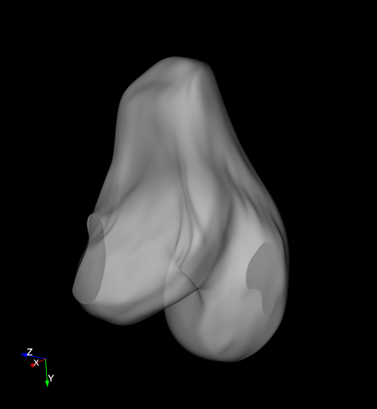
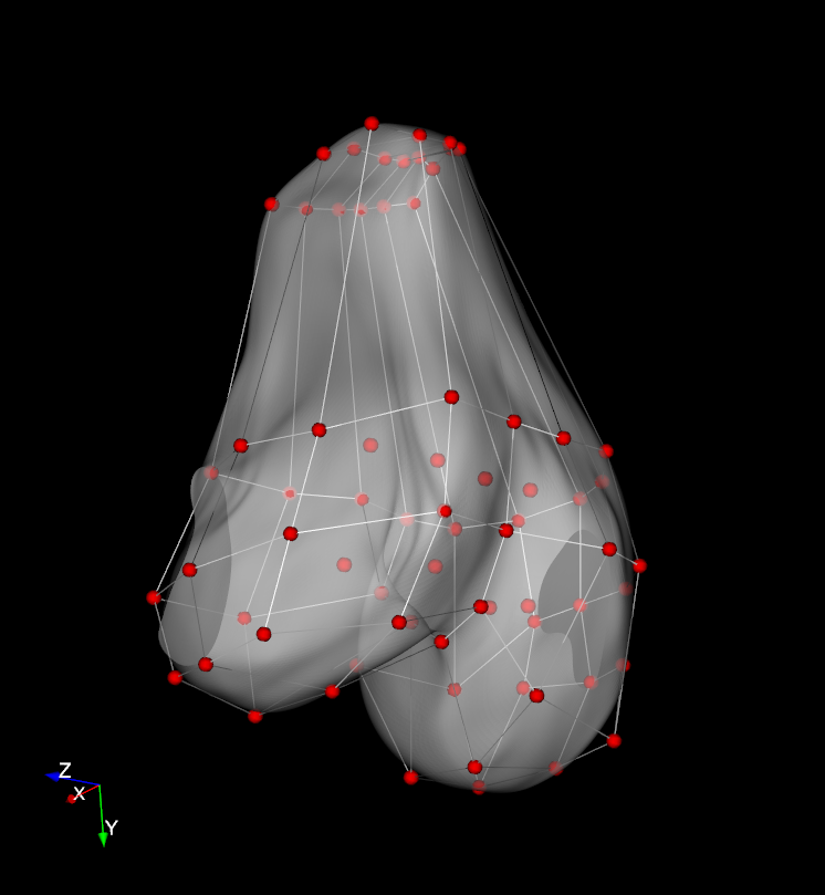
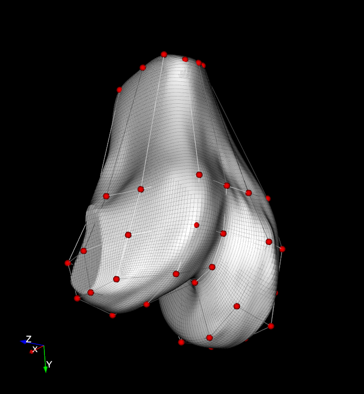
IA-FEMesh + rounded STL:
Software: IA-FEMesh, Version 1.0
Method: Quadrilateral Surface Meshing
Input: rounded STL triangulated surface geometry (i.e. no sharp edges in STL surface geometry)
Example Files:
OpenKnee, Gen. 1 model, femoral geometry (w/o holes): femur.stl,
IA-FEMesh block: femur_IA-FEMesh_Block.vtk
NOTES: block edges should be tangential to and circumscribed about surface geometry
LIMITATION: not able to control projection of block edge elements nodes to geometric edges!
- Run IA-FEMesh.
- Load surface geometry:
- Surface tab: select "Load" from drop-down menu (e.g. femur.stl).
- Change surface geometry opacity:
- Click on name of loaded surface geometry in Object Manager.
- e.g. set Opacity to 0.5 (out of 1.0 = opaque).
- Create a basic block:
- Block(s) tab: select "Create" from drop-down menu.
- Select "Create block from surface bounds".
- Click "Apply".
- Move basic block nodes to project to desire locations on surface:
- Block(s) tab: select "Build/Edit" from drop-down menu.
- Click hand button.
- Iteratively refine node positions:
- Rotate view (left mouse button outside of block geometry).
- Move node in planes perpendicular to view.
- Rotate view orthogonal to first view.
- Move node to final desired location.
- Click "Cancel" to finish.
- Partition block to refine block geometry to match surface geometry:
- Block(s) tab: select "Build/Edit" from drop-down menu.
- Iteratively partition block and edit/move newly created nodes:
- Click "Split" button.
- Select an edge perpendicular to desired block partitioning dimension (turns green when selected).
- Click "Apply".
- Iteratively move nodes (as in prior step).
- Click "Cancel" to finish.
- Save block IF desired:
- Block(s) tab: select "Save" from drop-down menu.
- Select desired "Building Block" in drop-down menu.
- Click "Apply".
- Name "File name" as desired.
- Click "Save".
- Assign Mesh Seeds:
- Mesh tab: select "Assign/Edit Mesh Seeds" from drop-down menu.
- Select "Element Length" from drop-down menu.
- Click "Apply".
- Iteratively refine seed sizes:
- Select a block edge in the 3D view to refine seeding for a particular partition of the block (vectors showing partition dimension will appear, i.e. Rx (red), Ry (green), Rz (blue)).
- Make desired partition dimension seeding either smaller or larger to decrease or increase the seed size respectively.
- Click "Cancel" to finish.
- Create mesh:
- Mesh tab: select "Create" from drop-down menu.
- Select "Surface Mesh", select "quad" (square).
- Specify "Node" and "Element" Label names.
- Click "Apply".
- Inspect mesh quality:
- Quality tab: select "Evaluate/Display Mesh Quality" from drop-down menu.
- Select Metric from drop-down menu: e.g. "Jacobian"
- Click "Cancel" to finish.
- Iteratively smooth mesh IF needed:
- Quality tab: select "Mesh Improvement" from drop-down menu.
- Set "Smoothing Iterations": e.g. 5.
- Click "Apply".
- Export mesh:
- Mesh tab: select "Export ABAQUS File" from drop-down menu.
- Select desired "Mesh" in drop-down menu.
- Click "Apply".
- Name "File name" as desired.
- Click "Save".
Example file results:
IA-FEMesh quad surface mesh: femur_IA-FEMesh_SurfMesh.vtk


HEXAHEDRAL MESHING
Model components: deformable bodies, volumetric (i.e. cartilage, ligaments, menisci)
IA-FEMesh + rounded STL:
Follow the corresponding procedure from the Quadrilateral Meshing section above, besides the following step:
- Create mesh:
- Mesh tab: select "Create" from drop-down menu.
- Select "Volumetric Mesh", select "hex" (cube).
- Specify "Node" and "Element" Label names.
- Click "Apply".
Salome Sub-Meshing + Hex-topology IGES:
Software: Salome 7.5.1
Method: Hexahedral Sub-Meshing (NOTE: tried Salome HEXABLOCK meshing, but face elements were twisted due to edge curvature)
Input: IGES parametric surface/volume geometry with hexahedral topology (i.e. 8 nodes, 12 edges, 6 faces)
Example Files:
OpenKnee, Gen. 1 model, lateral tibia cartilage geometry: lat_tibial_cartilage.igs,
Salome meshing script: lat_tibial_cartilage_Salome_HEX.py
- Run Salome.
- Activate "New" Geometry Module.
- Load IGES file:
File -> Import -> IGES (e.g. lat_tibial_cartilage.igs)
- If warned to "take units in account", select "Yes".
- If geometry is not visible in OCC 3D scene viewer:
- click 'Global Panning" button in OCC viewer.
- If 3D view manipulation shortcut + mouse button control is not working:
- click "Rotation" button in OCC viewer and rotate view a little, then shorcut + mouse will work.
- To volumetrically render the geometry, select:
View -> Display Mode -> Shading With Edges
- Check geometry information:
Measures -> What is
- Need to REPAIR the geometry IF:
- faces are not watertight
- it is NOT a solid.
- it does NOT have: 8 vertices, 12 edges, 6 wires, 6 faces.
- IF geometry REPAIR is needed:
- IF edges of faces are not watertight, SEW the geometry:
Repair -> Sewing
- Select shape: loaded geometry (e.g. lat_tibial_cartilage_1)
- Iteratively reduce the tolerance (from 1e-7) one order of magnitude at a time until geometry is valid:
- Check "What is" geometry until the result has: 6 wires, 6 faces, 1 shell.
- e.g. 1e-5 works with example geometry (lat_tibial_cartilage_1)
- OUTPUT GEOMETRY NAME: Sewing_#
- IF geometry is NOT SOLID:
New Entity -> Build -> Solid
- Select sewing: Sewing_#
- Check "What is" geometry: 6 wires, 6 faces, 1 shell, 1 solid.
- OUTPUT GEOMETRY NAME: Solid_1
- IF geometry has MORE THAN 8 vertices OR 6 edges:
Repair -> Remove Extra Edges
- Select: Solid_1
- Check "What is" geometry: 8 vertices, 12 edges, 6 wires, 6 faces, 1 shell, 1 solid.
OUTPUT GEOMETRY NAME: NoExtraEdges_1
- IF edges of faces are not watertight, SEW the geometry:
- Explode edges from solid geometry:
New Entity -> Explode
- Select Sub-shape Types: Edge
- Activate the Mesh module.
- Create a new mesh:
Mesh -> Create Mesh
Geometry: NoExtraEdges_1
- Mesh type: Hexahedral
- 3D tab:
- Algorithm: Hexahedron (i,j,k)
- 2D tab:
- Algorithm: Quadrangle (Mapping)
- Hypothesis:
- Transition: Standard
- Create 3 sub-meshes for each set of 4 matching hex-mesh block dimension edges:
Mesh -> Create Sub-mesh
Name: SubMesh_<dim> (e.g. SubMesh_z -or- SubMesh_3)
- Mesh: Mesh_1
- Geometry: interactively select 4 corresponding edges in Geometry hierarchy window
- use Shift or Ctrl to select multiple edges at once
e.g. for SubMesh_z, select: Edge_1, Edge_2, Edge_9, Edge_10
e.g. for SubMesh_x, select: Edge_3, Edge_4, Edge_11, Edge_12
e.g. for SubMesh_y, select: Edge_5, Edge_6, Edge_7, Edge_8
- 1D tab:
- Algorithm: Wire Discretisation
- Hypothesis: Nb. Segments
Name: Nb. Segments_<dim> (e.g. Nb. Segments_z)
Number of Segments: <desired #> (e.g. z = 3, x = 50, y = 50)
- Type of distribution: Equidistant distribution
- NOTE: create new Hypothesis for each block dimension: x,y,z
- Calculate mesh:
Mesh -> Compute
- Export mesh:
- Select mesh name in Geometry hierarchy window.
File -> Export -> UNV file.
- Name "File name" as desired.
- Click "Save".
Example file results:
Salome hex mesh: lat_tibial_cartilage_Salome_HEX.unv

Salome + STL:
Output
- Finite element mesh of tissue of interest; in human readable format, e.g., Abaqus input (INP) file, XML file, or as open format binary files, e.g., MED file, including
- node definitions (numbering and coordinates)
- element definitions (numbering, element-specific node numbers and connectivity)
- node set definitions (set name(s) and relevant node numbers)
- element set definitions (set name(s) and relevant element numbers)
- face definitions (numbering, face-specific node numbers and connectivity)
- surface set definitions (set name(s) and relevant face numbers)