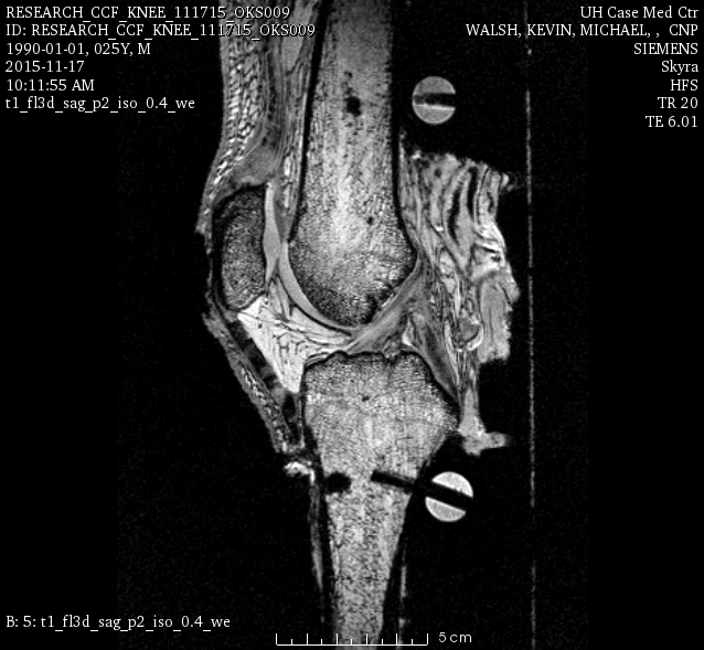
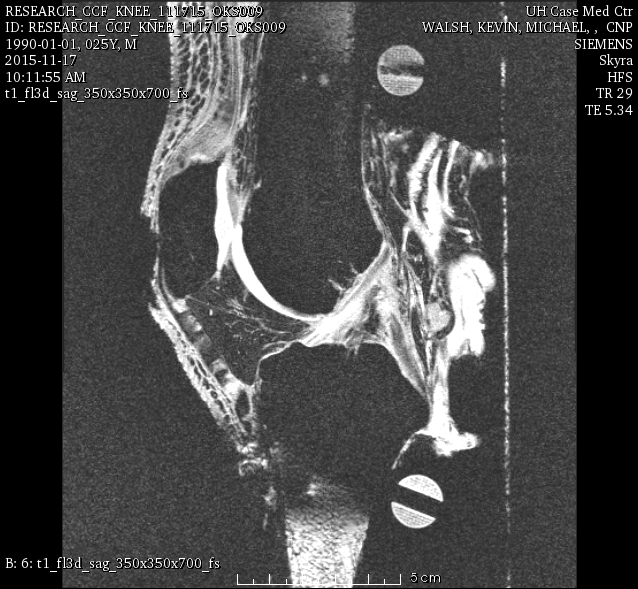
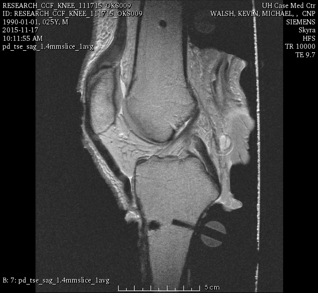
This page provides specifications of knee specimen OKS009. This is a young (likely healthy ![]() potentially damaged (see tibiofemoral joint testing notes)
potentially damaged (see tibiofemoral joint testing notes) ![]() ) male specimen candidate.
) male specimen candidate.
Specimen Characteristics
Left knee
Gender: Male
Age: 34 years
Race: White
Height: 1.8 m
Weight: 68.03 kg
BMI: 20
Serologically tested: Yes.
X-ray:
Not available
Experimentation
-- aerdemir 2015-11-16 14:51:54 All, please complete relevant sections of this page during and after experimentation.
Specimen
Reference Specification: Specifications/Specimens - Revision as of November 16, 2015
Leading Team Member: Snehal Chokhandre
Supporting Team Members: Ahmet Erdemir
Timeline:
- November 15, 2015 @ ~ 9:30 AM (specimen pulled out of freezer)
Data Location:
Specimen characteristics are provided in this wiki page.
Protocol Deviations:
- X-ray evaluation was not possible due to lack of X-ray imaging of the specimen.
Notes:
- None.
Specimen Preparation
Reference Specification: Specifications/SpecimenPreparation - Revision as of November 16, 2015
Leading Team Member: Tara Bonner
Supporting Team Members: Snehal Chokhandre, Craig Bennetts, Robb Colbrunn, Callan Gillespie, Ahmet Erdemir
Timeline:
- Thawing: ~9:30 AM November 15, 2015 - ~10:00 AM November 16, 2015
- Dissection: ~10:00 AM - ~11:30 AM November 16, 2015
- Assembly of Optotrak Base Plugs: ~ 12:15 PM - ~2:00 PM November 16, 2015
- Assembly of Registration Markers: ~2:00 PM - ~2:45 PM November 16, 2015
- Probing of Anatomical Landmarks: ~3:30 PM - ~3:40 PM November 16, 2015
- Probing of Registration Markers: ~3:40 PM - ~3:50 PM November 16, 2015
Data Location:
Data will be available as part of tibiofemoral joint mechanics data (see below).
Protocol Deviations:
- None.
Notes:
- Dissected and keeping skin-fat-muscle layers from thigh and shank.
- The orientation of the bone plugs for tibia and femur were adjusted to accommodate motion analysis marker in relation to pot.
- Skin and fat layers on the posterior side of the knee were removed to accommodate placement of the specimen in transportation fixture for imaging. This was necessitated by the large size of the knee.
- The femur registration markers were placed to medial, lateral, and posterior sides (alternative configuration).
- Tibia anatomical landmark measurements were in the order lateral plateau, medial plateau, lateral malleolus (x2), medial malleolus (x2).
- Femur anatomical landmark measurements were in the order lateral epicondyle, medial epicondyle, epiyhseal line (x4, anterior, inferior, posterior, superior),
- Patella anatomical landmark measurements were in the order lateral, medial, superior, inferior.
- The femur registration marker digitization sequence was medial, lateral, posterior.
- The tibia registration marker digitization sequence was lateral, medial, posterior.
- Dissected and keeping the femoral head.
- Dissected and keeping bone from femoral and tibial shafts.
- More screws (to assemble the Optotrak bone base plugs) need to be purchased for next experimentation.
Joint Imaging
Specimen Preparation
Reference Specification: Specifications/SpecimenPreparation - Revision as of November 16, 2015
Leading Team Member: Craig Bennetts
Supporting Team Members:
Timeline: Snehal Chokhandre
- ~4:00 PM - ~4:30 PM November 16, 2015
Data Location:
Protocol Deviations:
- None.
Notes:
- Skin and fat at the posterior region of the knee were removed to accommodate placement in the transportation fixture.
Imaging
Reference Specification: Specifications/ExperimentationAnatomicalImaging - Revision as of November 17, 2015
Leading Team Member: Craig Bennetts
Supporting Team Members: Snehal Chokhandre
Timeline:
- Specimen Placement in Transportation Fixture: ~8:30 AM - ~9:30 AM November 17, 2015
- Imaging: ~10:00 AM - ~12:00 PM November 17, 2015
Data Location:
Data was received from the imaging facilities and uploaded to in-house data management server (http://cobicore.lerner.ccf.org/midas; only accessible within Cleveland Clinic network). Raw DICOM files were stored in the folder Open Knee(s) --> Private --> oks009 --> MRI --> DICOM
DICOM files were converted to NIfTI files, stored in the folder Open Knee(s) --> Private --> oks009 --> MRI --> NIFTI of the in-house data management server. NIfTI files were also disseminated to the public in the 'Downloads' section of the project website, https://simtk.org/home/openknee, under the package oks009.
Data storage and dissemination were accomplished based on the updated imaging specifications, see Revision as of December 7, 2015.
Protocol Deviations:
- None.
Notes:
Joint Mechanics
Equipment Preparation
Reference Specification: Specifications/PressureCalibration - Revision as of November 17, 2015
Leading Team Member: Robb Colbrunn
Supporting Team Members: Callan Gillespie
Timeline:
- Equilibration: ~ 12:15 PM - ~ 12:30 PM November 17, 2015
- Calibration: ~ 7:00 AM - ~8:00 AM November 18, 2015
Data Location:
Protocol Deviations:
- None.
Notes:
- None.
Specimen Preparation
Reference Specification: Specifications/SpecimenPreparation - Revision as of November 17, 2015
Leading Team Member: Tara Bonner
Supporting Team Members: Robb Colbrunn, Callan Gillespie
Timeline:
- Specimen preparation for TFJ testing: ~12:15 PM - ~2:00 PM November 17, 2015
- Specimen preparation for PFJ testing: ~7:30 AM - ~9:30 AM November 18, 2015
Data Location:
Protocol Deviations:
- None.
Notes:
- During insertion of pressure sensor to the patellofemoral joint, a fat bursa on the lateral side of the joint was observed.
Testing
Reference Specification: Specifications/ExperimentationJointMechanics - Revision as of November 17, 2015
Leading Team Member: Tara Bonner, Robb Colbrunn
Supporting Team Members: Callan Gillespie, Ahmet Erdemir
Timeline:
- Specimen Mounting for TFJ testing: ~2:00 PM - ~2:45 PM November 17, 2015
- Testing of TFJ: ~4:00 PM (robot malfunction) then ~7:00 PM - ~10:00 PM November 17, 2015
- Specimen Mounting for PFJ testing: ~ 10:00 AM - November 18, 2015
- Testing of PFJ: ~12:00 PM - ~ 1:30 PM November 18, 2015
Data Location:
Data was received from the robotics testing facility and uploaded to in-house data management server (http://cobicore.lerner.ccf.org/midas; only accessible within Cleveland Clinic network). Zipped folders were stored in the folder Open Knee(s) --> Private --> oks009 --> JointMechanics under relevant joint related folders.
Zipped folders were extracted and organized in the dissemination folder under Open Knee(s) --> Private --> oks009 --> !
JointMechanics --> DISSEMINATION of the in-house data management server. DISSEMINATION folder was downloaded and disseminated to the public in the 'Downloads' section of the project website, https://simtk.org/home/openknee, under the package oks009.
Data storage and dissemination were accomplished based on the updated joint mechanics testing specifications, see Revision as of December 8, 2015.
Protocol Deviations:
- None.
Notes:
During tibiofemoral joint testing, the first passive flexion test completed. During extension, the robot malfunction resulted in large forces and moments to be applied on the knee (>4,000 N compression unfiltered raw data from force transducer in JCS? possibly saturated (check movements based on knee anatomical JCS measured by Optotrak); >1,000 N posterior; >400 N lateral; >30 Nm flexion; >25 Nm valgus, >5 Nm internal rotation - for exact magnitudes check the relevant tdms file). This may have resulted in damage of knee structures. In the second passive flexion test, flexion was completed yet during extension the same malfunction was observed. It may be possible to compare the first passive flexion curve (response of the intact joint) with the second passive flexion curve (response of the potentially damaged joint) to assess any discrepancies due to tissue failure. It may be necessary to consider this specimen as a damaged specimen. The group decided to collect tibiofemoral joint testing data per specifications anyways. The loading and kinematic profiles of the abrupt extension profiles were saved to be able to simulate potentially damage inducing simulation scenarios. If damaged, the laxity and combined loading data may serve modeling & simulation of an injured knee. Callan has a video of the second passive flexion/extension loading profile which may indicate what the robot was doing. He will upload the video to the data management system. The group needs to evaluate the joint critically during dissection, documenting tissue state by taking pictures.
- Following robot maintenance, the tibiofemoral joint testing restarted. Passive flexion testing data was qualitatively compared to first passive flexion test (before robot malfunction and large loads being applied to the knee). There was an agreement but this may not warrant lack of any damage to ligaments, menisci, and cartilage.
- During tibiofemoral joint testing, posterior drawer tests (for 30, 60, and 90 degrees flexion) were repeated due to non-zero (unminimized) external rotation moment.
- Specifications of all force transducers, specifically the Theta transducer, should be added to the wiki page on infrastructure for joint mechanics testing.
Before patellofemoral joint testing, troubleshooting in simVitro (robot control and data collection) needed to be performed. This delayed start of patellofemoral joint testing. Previous scripts to move from tibiofemoral joint testing placement settings to patellofemoral joint testing placement settings did not work due to recent updates to SimVitro. This step was handled manually and the script will need to be updated in future. This does not affect the data.
- During patellofemoral joint testing, for 60 degrees flexion, the tibiofemoral joint equilibrium state to represent passive flexion seemed deviating from its original state. It may be possible that multiple equilibrium states may exist, i.e particularly for internal/external rotation. The equilibrium state was found without any quadriceps load (rather than a minimal ~10 N load) and experiment was conducted. Testing for 45 degrees flexion was also repeated; the pressure sensor location was adjusted before these repeat tests. It should be noted that tibiofemoral joint kinematics and kinetics were collected at all times.
- During patellofemoral joint testing, for 60 degrees flexion and 200 N quadriceps loading, kinematics/kinetics data were collected twice whereas pressure data were collected once. The latter kinematics/kinetics data correspond to the pressure data.
Tissue Mechanics
Specimen Preparation
Reference Specification: Specifications/SpecimenPreparation - Revision as of November 18, 2015
Leading Team Member: David Brigati, MD
Supporting Team Members: Snehal Chokhandre, Craig Bennetts, Will Zaylor
Timeline:
- Soft tissue dissection: ~2:00 PM - ~ PM November 18, 2015
- Cartilage dissection: ~ AM - ~ PM November 19, 2015
Data Location:
Protocol Deviations:
- None.
Notes:
- The dissection was guided by David Brigati, MD, a resident working with Morgan Jones, MD. The dissection targeted for primary and secondary tissues per specifications, the order of dissection was decided upon by the resident.
- A fibrous connection between anterior and posterior cruciate ligaments was observed.
- A cartilage defect on the posterior.superior,lateral side of the femur (contact corresponding to deep flexion) was observed during dissection. It may be good to check if this defect is apparent in the magnetic resonance images.
- Per David, the joint and its tissue structures do not have any apparent damage that can be attributed to the undesirable tibiofemoral joint loading applied during the tests (see notes above).
- Various secondary tissues were dissected; in particular transverse ligament, popliteus, mpfl, capsule, fat bursa.
Testing
Reference Specification:
Leading Team Member:
Supporting Team Members:
Timeline:
Data Location:
Protocol Deviations:
- None.
Notes:
- None.
Data Analysis
Registration
Note: During patella registration, the data was not stored in the tdms file (Registration marker relative placement.tdms). Since the same patella marker and reference marker were used for oks008, the tdms file and State.cfg files from oks008 can be used in place to complete the patella registration for this specimen.
Spherical Markers
- Femur
<Posterior>oks009_MRG_FMR-P_WAV_01.stl
<Lateral>oks009_MRG_FMR-L_WAV_01.stl
<Medial>oks009_MRG_FMR-M_WAV_01.stl
- Tibia
<Posterior>oks009_MRG_TBR-P_WAV_01.stl
<Lateral>oks009_MRG_TBR-L_WAV_01.stl
<Medial>oks009_MRG_TBR-M_WAV_01.stl
- Patella
<Superior>oks009_MRG_PTR-S_WAV_01.stl
<Lateral>oks009_MRG_PTR-L_WAV_01.stl
<Medial>oks009_MRG_PTR-M_WAV_01.stl
Digitizing Order
- Tibia:
- Sphere 1 = Lateral
- Sphere 2 = Medial
- Sphere 3 = Posterior
- Femur:
- Sphere 1 = Medial
- Sphere 2 = Lateral
- Sphere 3 = Posterior
Joint Mechanical Testing
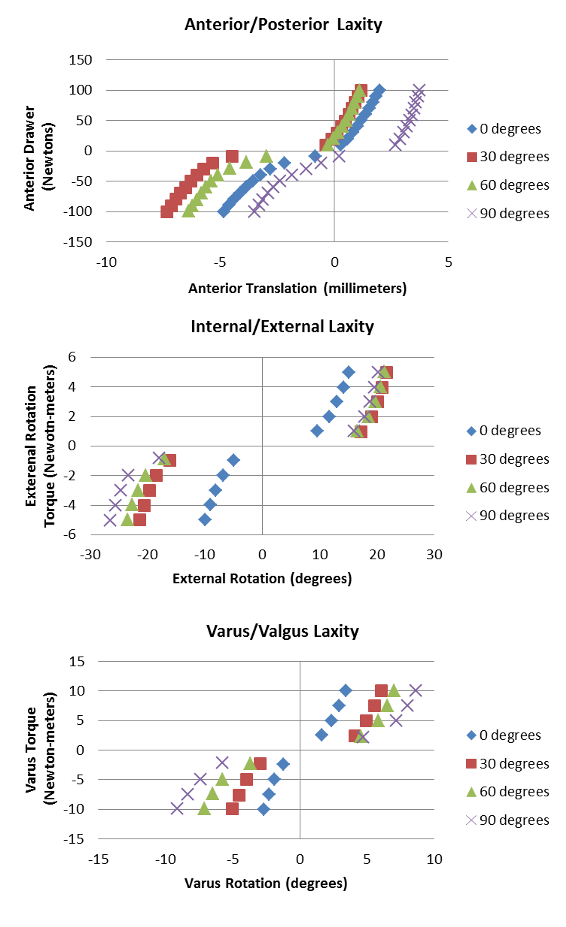
Pictured below are the Anterior Posterior laxity graph, the IR/ER laxity graph, and the Varus/Valgus laxity graph.


