Relevant publication:
Schimmoeller T, Colbrunn R, Nagle T, Lobosky M, Neumann EE, Owings TM, Landis B, Jelovsek JE, Erdemir A. Instrumentation of Off-The-Shelf Ultrasound System for Measurement of Probe Forces During Freehand Imaging. J Biomech (in press).
Equipment
Ultrasound
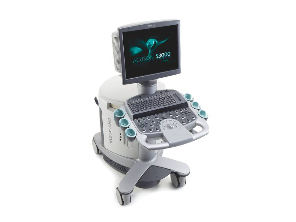
Ultrasound Transducers
- 9L4 Transducer
- Frequency Bandwidth: 4 – 9 MHz (Linear)
- Transducer head dimensions: 4.5 x 1.5 cm
- Imaging depth: 5-6 cm
- Compatible With: ACUSON S1000™, S2000™, and S3000™ ultrasound system
- Exam Types: Breast, Cardiovascular, Fetal Echo, Musculoskeletal, OB/GYN, Pediatric Abdomen, Pediatric Hip, Pelvis, Penile, Peripheral Vascular, Testicle, Thyroid
- Design Attributes:
- Multi-D matrix transducer
- Ergonomically designed form factor
- Lightweight transducer with flexible cable
User-selectable MultiHertz™ imaging
- Harmonic compounding

- 14L5 Transducer
- Frequency Bandwidth: 5 – 14 MHz (Linear)
- Transducer head dimensions: 4.5 x 0.8 cm
- Imaging depth: 2-6 cm
- Compatible With: ACUSON S1000™, S2000™, and S3000™ ultrasound system
- Exam Types: Breast, Cardiovascular, Musculoskeletal, Penile, Peripheral Vascular, Testicle, Thyroid
- Design Attributes:
- Multi-D matrix transducer
- Ergonomically designed form factor
- Lightweight transducer with flexible cable
- Virtual format imaging
User-selectable MultiHertz™ imaging

For a list of available ultrasound transducers that were not used in this study, see TransducersAvailable.
Force Transducer
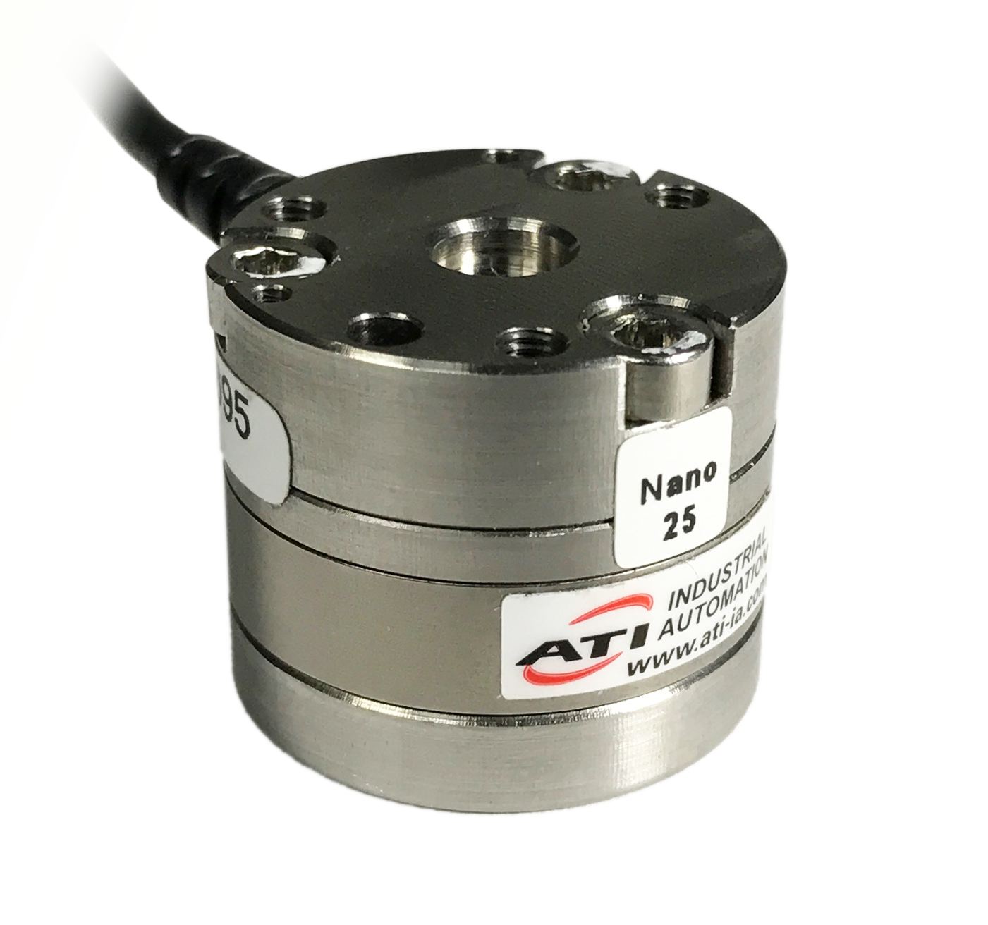
- Nano 25 (ATI Industrial Automation) with Dual Calibration
- SI-125-3 Calibration
- Range
- Fx,Fy-125 N, Fz-500 N, Tx,Ty-3 Nm, Tz-3 Nm,
- Resolution
- Fx,Fy-1/48 N, Fz-1/16 N, Tx,Ty-1/1320 Nm, Tz-1/2640 Nm,
- SI-250-6 Calibration
- Range
- Fx,Fy-250 N, Fz-1000 N, Tx,Ty-5 Nm, Tz-3.4 Nm,
- Resolution
- Fx,Fy-1/24 N, Fz-1/8 N, Tx,Ty-1/660 Nm, Tz-1/1320 Nm,
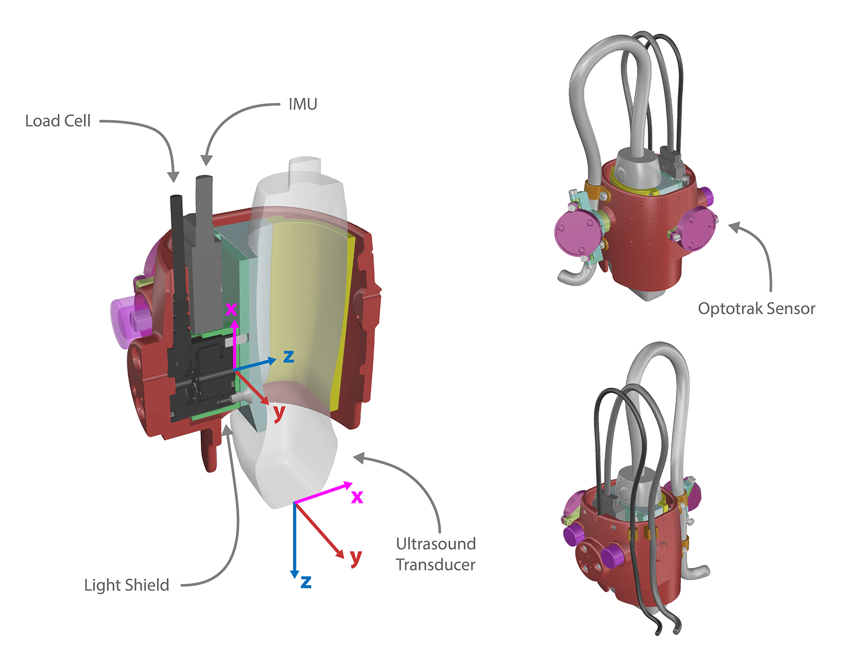
- Note: a light shield was designed to encase the load cell to prevent measurement fluctuation due to changes in ambient light.
Inertial Measurement Unit
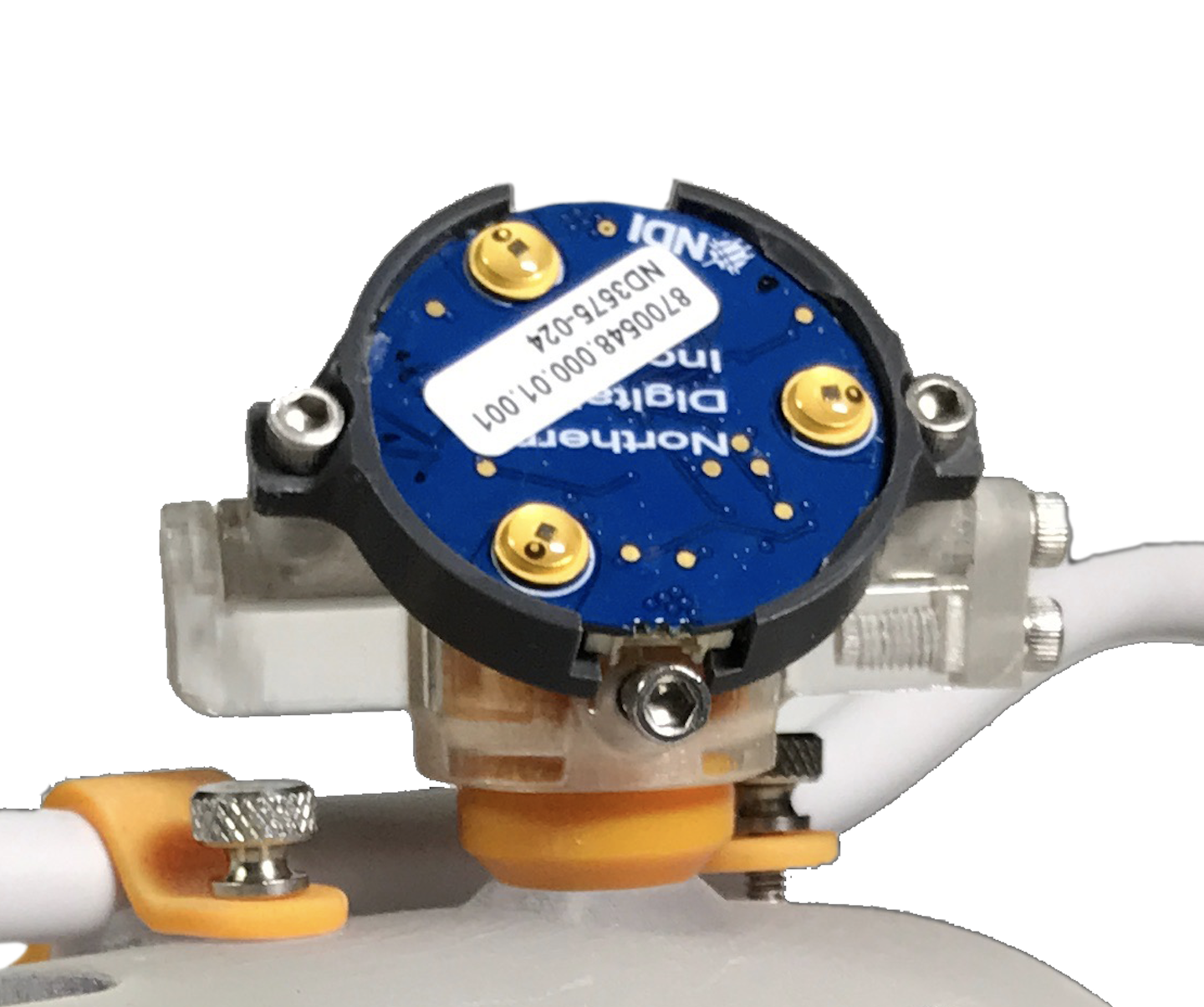
VectorNav Inertial Measurement Unit (IMU) and Attitude Heading Reference System (AHRS) VN-100 Rugged (http://www.vectornav.com/products/vn100-rugged) is a sensor that will be mounted into the ultrasound probe handle to calculate orientation of the probe throughout the experiment. This orientation, relative to gravity, can be used to gravity compensate the load cell output and provide probe contact loads independent of orientation.
The VectorNav API has a .NET library which allows for integration in the data acquisition system. Communication is via USB/serial port.
In the Binary Data File below, IMU is referred to as OrientationSensor.

Motion Capture (In vitro only)
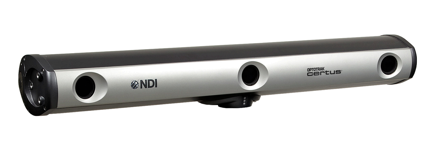
Optotrak Certus camera with Smart Cluster LED https://www.ndigital.com/msci/products/optotrak-certus/
- NDI First Principles software used to interface data to custom LavVIEW software
Integration
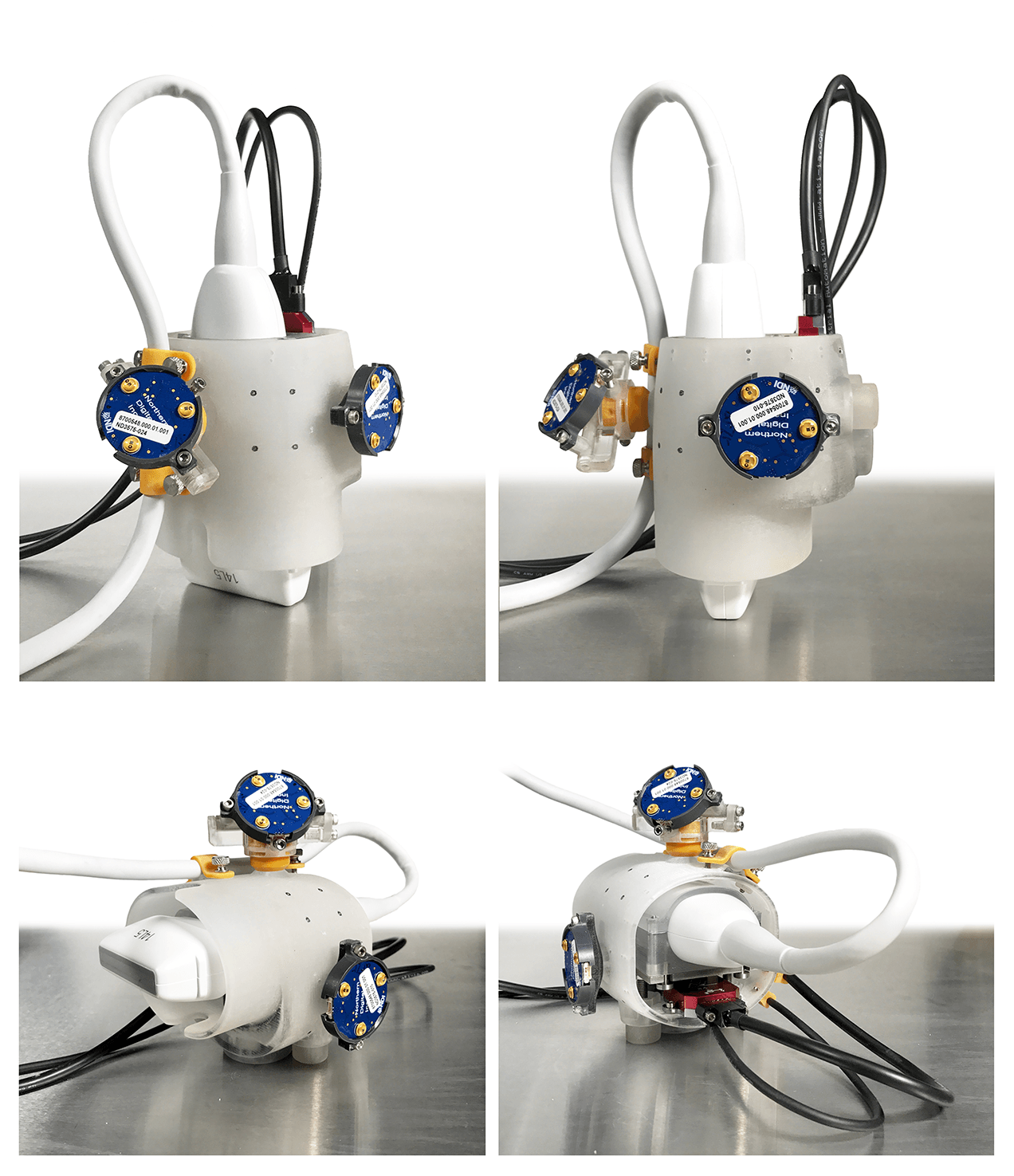
Physical Assembly
- Loads are measured in load transducer coordinate system but also represented in ultrasound probe coordinate system (origin and orientation) as the loads applied by the probe on the segment.
- Analysis of Load Cell Placement to minimize Torque
- See analysis in attached file
Data Collection
- The load cell will be attached to the DAQ system with the USB-6289 as the DAQ interface.
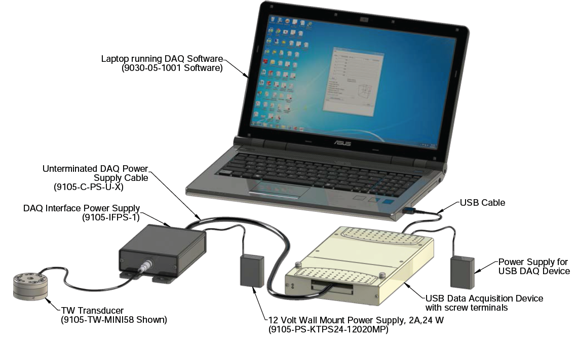
- USB-6289 (National Instruments)
- 32 analog inputs (18-bit); 625 kS/s single-channel (500 kS/s aggregate)
- 4 analog outputs (16-bit, 2.8 MS/s); 48 digital I/O (32 clocked); two 32-bit counters
- Use mass-termination version with SCC signal conditioning; OEM version available
- NI signal streaming for sustained high-speed data streams over USB
Compatibility with LabVIEW, LabWindows™/CVI, and Measurement Studio for Visual Studio .NET
NI-DAQmx driver software and LabVIEW SignalExpress LE interactive data-logging software
Ultrasound and Load Data Synchronization
- The in vivo testing will consist of a subject, technician, ultrasound system (with load cell attached to probe), and a laptop running custom software. This software has a two-fold purpose: Collect the ultrasound probe load cell data and manage data sets by keeping track of the anatomical location and orientation of each experiment run. An experiment run is when the technician collects ultrasound images and force data at a specified anatomical location, in a specified orientation. The software will automatically assign a unique, sequential, 3 digit experiment run number to each run. Even if the technician decides to repeat data for a given anatomical location and orientation, the experiment run number will be incremented and no run numbers will duplicate. In this way, the run number defines a unique instance.
- The custom software will pair the anatomical location and orientation with the load cell data. However, the ultrasound images are on a different machine and are not inherently temporally synchronized with the load cell data. Nor, is it guaranteed to know which experiment run matches which ultrasound image set. For this reason, a technique for registering these two disconnected data sets needs to be created. The plan is to encode into the ultrasound EKG signal a pulse train which can be used to time align and data set match. The signal will be generated by an analog output on the data acquisition board attached to the laptop.
- The signal sent to the ultrasound must mimic a typical EKG signal. The ultrasound has the ability to record heart rate by measuring the distance between each R-Wave of a QRS complex. This data is stored in the metadata of the DICOM file produced by the ultrasound as an R-Wave time vector (a vector of time intervals). The pulse train sent to the ultrasound EKG will be designed to simulate a typical EKG wave form by matching its width and amplitude. By doing so, we can send a unique, encoded signal with specified R Wave time vector to the ultrasound and later match the R Wave time vector calculated by the ultrasound with the signal produced by the custom software.
- Limitations are the sampling rate of the ultrasound, roughly 33 Hz, and the algorithm the ultrasound uses to begin and end R-Wave analysis. By providing sufficient space between pulses, using a start and end pulse as primers, and simulating typical EKG wave lengths and peaks, both limitations can be overcome.
Signal Alignment:
- To time align the signals, the average difference between the peaks of the pulse and the corresponding R-Wave time vector is calculated. For example, the first peak of the pulse is subtracted from the first R-Wave time interval , then the second, third etc. This difference, delta T, is used to align the R-Wave time interval to the pulse via a best fit optimization. Now, the time between the start of the ultrasound and the start of the pulse train is known plus or minus 30 ms, and the two data sets can be aligned and associated.
- The alignment has a standard deviation of roughly 30 ms, the sampling rate of the ultrasound, making the best fit appropriate.
File Association:
- The following diagrams describe the file association process. A custom python script was written to analyze and associate the R-Waves and pulse peaks.
- Find delta T between each R-Wave and its corresponding pulse peak.
- If the number of R-Waves do not equal the number of pulse peaks, the files do not match, therefor that TDMS file is temporarily skipped and checked again with a different DICOM file.
- Find average delta T
- Shift R-Waves to the left by average delta T. The R-Waves are now best fit to the pulse peaks.
- Find delta T between each corresponding pulse peak and shifted R-Wave.
- If each delta T is less than 95 ms, the files are a match. Else, one or more R-Waves is in a different location than its associated peak, hence can not match. The limit is set higher than the sampling rate of the ultrasound because during optimization, if any of the R-Waves were on the opposite side of the peak, its error will be increased as others are decreased.
- This margin of 95 ms is sufficient because each potential bit location is 300 ms. A +/- 95 ms margin not enough to incorrectly identify an R-Wave.
- Decode the pulse train. If a pulse is detected in a bit location, which are every 300 ms, then a 1 is recorded, else a 0. The pulse train is encoded in reverse binary therefore it is decoded in reverse.
- Convert binary to decimal, giving
- experimental run number (10 bit) example
- Binary = 0000111100
- Decimal Equivalent = 60
- subject ID (8 bit) example
- Binary = 00100101
- Decimal Equivalent = 37
- experimental run number (10 bit) example
- Find delta T between each R-Wave and its corresponding pulse peak.

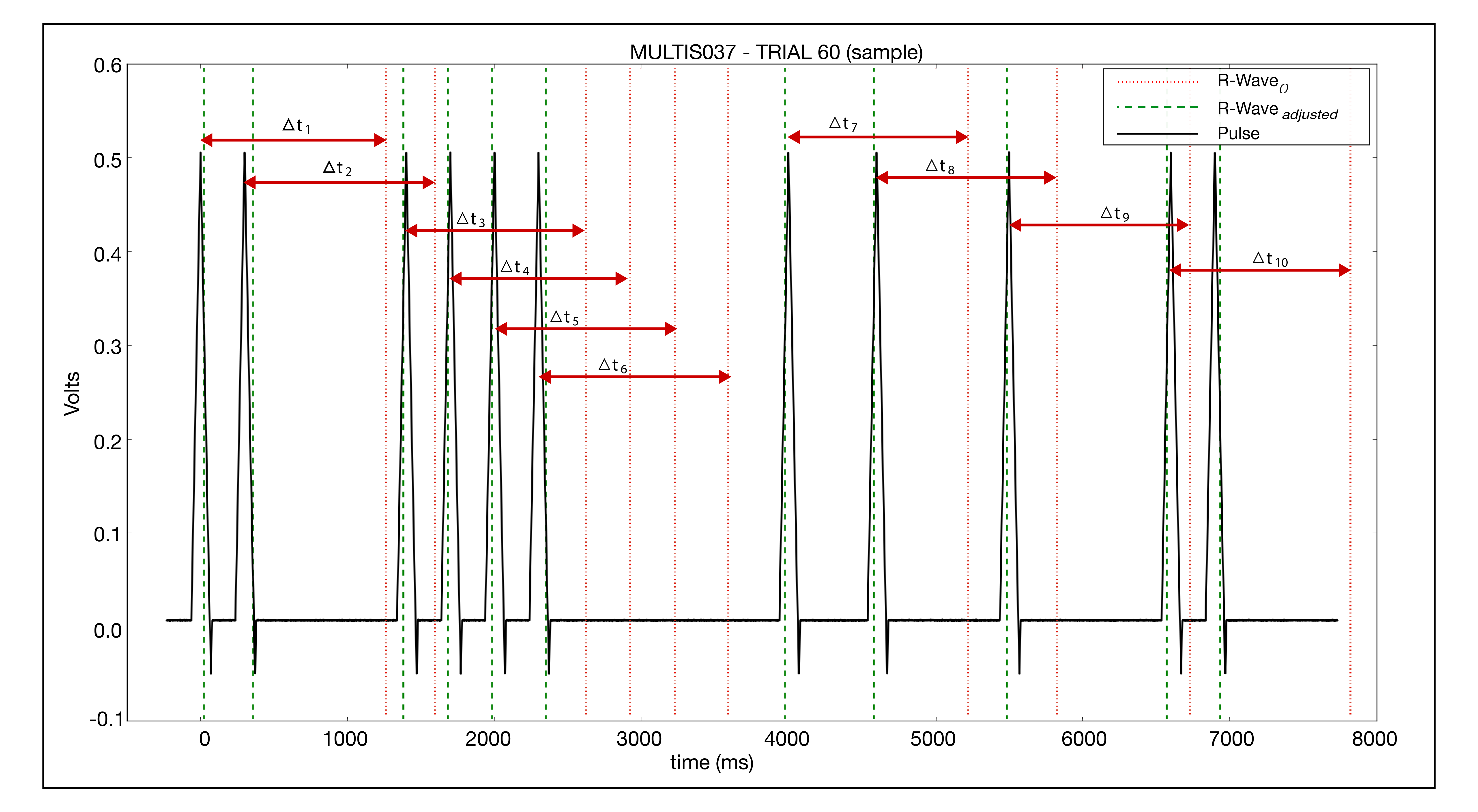
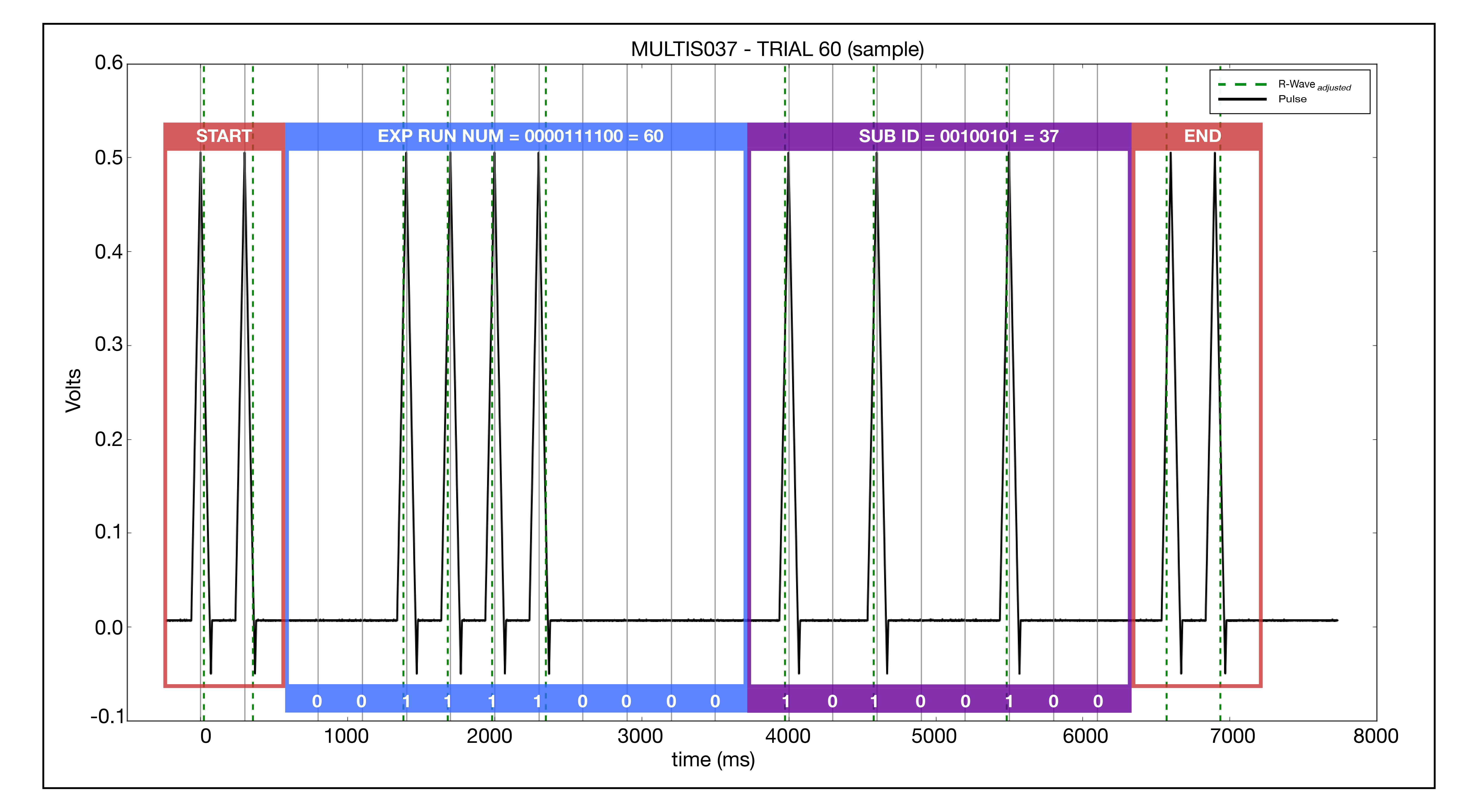
- This signal will be input to the ultrasound system via the Auxiliary 1 ECG input. It is intended to take ECG waveforms from other devices such as what your team is designing. It can handle up to a 1V input. In this way, the no-signal output should be 0V and then the on and off will be 0.5V and 0.005V respectively.

Test pulse train…
- Set up ultrasound machine:
- Turn on
- Change mode to MSK
- Go to wrench button (system configuration)
- Physio System
- Change sweep speed to 1
- Change gain to Manual.
- Click save
- Click on x to close.
- If the trace doesn’t show up, unplug and replug.
Analog Hardware and Pulse Configuration:
- Plug NI cable into AI16-31.
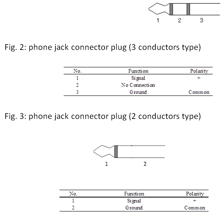
- Plug trigger into AO3. Which are pins 21 (+) and 55 (-).
Ultrasound video of one indentation trial showing the EKG signal and forces all in sync:
ExpRunPulseTrain.mp4
Data File/Folder Naming Convention
Documentation::
2015CB-047-002.B Data File Contents_CMULTIS.pdf
2015CB-047-001.D Data File Contents_MULTIS.pdf
Example_Subject_Configuration.xml
Example_Sensor_Configuration.cfg
Example_State_Configuration.cfg
coordinate_sys_transformations.pdf
Subject Configuration File
- Subject data is stored in a subject configuration file (.xml format)
- Subjects are identified by a number
- Subject information includes:
- Subject ID
- For in-vivo: Convention is MULTIS###-# where ### is an auto incremented unique for each subject. # is a number starting at 1. This tag is auto incremented if the operator chooses to retest the subject -2, -3, etc.
- For in-vitro: Convention is CMULTIS###-# where ### is an auto incremented unique for each subject. # is a number starting at 1. This tag is auto incremented if the operator chooses to retest the subject -2, -3, etc.
- Test Date
- Test Type (New or retest)
- Demographics
- Age
- Gender
- Ethnicity
- Race
- Height
- Body Mass
- Lifestyle (Extremely Inactive, Sedentary, Moderately Active, Active, Extremely Active)
- Subject ID
- Collected Data Structure - An array of structures of the following data elements
- Ultrasound Location
- Data collected (boolean)
- Location File Abbreviation
- Data File Array - Each ultrasound location may be measured more than once. Data is never deleted. Displayed data will always be the last element in the array.
- Path on disk
- Data accepted (Boolean)
- Time Stamp
- Experiment Run Number - This is the same number that was transmitted to the ultrasound machine via the signal outlined above.
- Anatomical Measurements
- Segment (upper arm, lower arm, upper leg, lower leg)
- Length
- Distal circumference
- Central circumference
- Proximal circumference
- Landmark (shoulder, elbow, hip, knee) to distal circumference
- Landmark (shoulder, elbow, hip, knee) to central circumference
- Landmark (shoulder, elbow, hip, knee) to proximal circumference
- Segment (upper arm, lower arm, upper leg, lower leg)
Data File Example - Example_Subject_Configuration.xml
Binary Data File
In Vivo
- Force and orientation data will be stored in a binary TDMS data file. TDMS is a proprietary National Instruments file format, but there are many readers (open source and otherwise) that can be used to read in the data from these files.
- File contents: * Group/Channel
- /'Experiment Run details'
- /'Experiment Run details'/'Sensor file path'
- /'Experiment Run details'/'State file path'
- /'Experiment Run details'/'Ultrasound Probe'
- /'Experiment Run details'/'Load Cell Calibration'
- /'Experiment Run details'/'Ultrasound Weight (N)'
- /'Experiment Run details'/'Ultrasound Center of Mass (mm)'
- /'Experiment Run details'/'Load Cell Offsets (N, Nm)'
- /'Sensor.Load Cell'
- /'Sensor.Load Cell'/'Load Cell_Fx'
- /'Sensor.Load Cell'/'Load Cell_Fy'
- /'Sensor.Load Cell'/'Load Cell_Fz'
- /'Sensor.Load Cell'/'Load Cell_Mx'
- /'Sensor.Load Cell'/'Load Cell_My'
- /'Sensor.Load Cell'/'Load Cell_Mz'
- /'Sensor.Orientation Sensor'
- /'Sensor.Orientation Sensor'/'Orientation Sensor_x'
- /'Sensor.Orientation Sensor'/'Orientation Sensor_y'
- /'Sensor.Orientation Sensor'/'Orientation Sensor_z'
- /'Sensor.Orientation Sensor'/'Orientation Sensor_r'
- /'Sensor.Orientation Sensor'/'Orientation Sensor_p'
- /'Sensor.Orientation Sensor'/'Orientation Sensor_w'
- /'Sensor.Run Number Pulse Train'
- /'Sensor.Run Number Pulse Train'/'Run Number Pulse Train'
- /'State.6-DOF Load'
- /'State.6-DOF Load'/'6-DOF Load Fx'
- /'State.6-DOF Load'/'6-DOF Load Fy'
- /'State.6-DOF Load'/'6-DOF Load Fz'
- /'State.6-DOF Load'/'6-DOF Load Mx'
- /'State.6-DOF Load'/'6-DOF Load My'
- /'State.6-DOF Load'/'6-DOF Load Mz'
- /'State.Load Cell Position 2 RB'
- /'State.Load Cell Position 2 RB'/'Load Cell Position 2 RB x'
- /'State.Load Cell Position 2 RB'/'Load Cell Position 2 RB y'
- /'State.Load Cell Position 2 RB'/'Load Cell Position 2 RB z'
- /'State.Load Cell Position 2 RB'/'Load Cell Position 2 RB roll'
- /'State.Load Cell Position 2 RB'/'Load Cell Position 2 RB pitch'
- /'State.Load Cell Position 2 RB'/'Load Cell Position 2 RB yaw'
- /'Experiment Run details'
- File Naming Convention
- "Experiment Run Number"_"Subject ID"_"Limb Segment"_"Location"_"Test Type"-"Trial Number Index".tdms
- Where:
- Experiment Run Number: 3 digit number that gets auto-incremented for each tdms file (order in which data is collected for each specimen)
- Subject ID : MULTIS001-1
- Limb Segment: UA = Upper Arm, UL = Upper Leg, LA = Lower Arm, LL = Lower Leg
- Location: Two letters. First Letter - (A)nterior, (P)osterior, (M)edial, (L)ateral. Second Letter - (P)roximal, (D)istal, (C)entral.
- Test Type: I = Indentation, A = Anatomy (no indentation)
- Trial Number Index: auto-incremented for each trial. i.e. if the location is tested more than once the subsequent data files will be -2, -3, etc.
- Example Data File Name: 034_Multis033-2_UA_AP_I-4.tdms
- Where:
- "Experiment Run Number"_"Subject ID"_"Limb Segment"_"Location"_"Test Type"-"Trial Number Index".tdms
In Vitro
- Force, orientation, and position (Optotrak) data will be stored in a binary TDMS data file.
- /'Experiment Run details'
- /'Experiment Run details'/'Sensor file path'
- /'Experiment Run details'/'State file path'
- /'Experiment Run details'/'Ultrasound Probe'
- /'Experiment Run details'/'Load Cell Calibration'
- /'Experiment Run details'/'Ultrasound Weight (N)'
- /'Experiment Run details'/'Ultrasound Center of Mass (mm)'
- /'Experiment Run details'/'Load Cell Offsets (N, Nm)'
- /'Sensor.Humerus'
- /'Sensor.Humerus'/'Humerus_smart_02.x'
- /'Sensor.Humerus'/'Humerus_smart_02.y'
- /'Sensor.Humerus'/'Humerus_smart_02.z'
- /'Sensor.Humerus'/'Humerus_smart_02.r'
- /'Sensor.Humerus'/'Humerus_smart_02.p'
- /'Sensor.Humerus'/'Humerus_smart_02.w'
- /'Sensor.Load Cell'
- /'Sensor.Load Cell'/'Load Cell_Fx'
- /'Sensor.Load Cell'/'Load Cell_Fy'
- /'Sensor.Load Cell'/'Load Cell_Fz'
- /'Sensor.Load Cell'/'Load Cell_Mx'
- /'Sensor.Load Cell'/'Load Cell_My'
- /'Sensor.Load Cell'/'Load Cell_Mz'
- /'Sensor.Orientation Sensor'
- /'Sensor.Orientation Sensor'/'Orientation Sensor_x'
- /'Sensor.Orientation Sensor'/'Orientation Sensor_y'
- /'Sensor.Orientation Sensor'/'Orientation Sensor_z'
- /'Sensor.Orientation Sensor'/'Orientation Sensor_r'
- /'Sensor.Orientation Sensor'/'Orientation Sensor_p'
- /'Sensor.Orientation Sensor'/'Orientation Sensor_w'
- /'Sensor.Radius'
- /'Sensor.Radius'/'Radius_smart_02.x'
- /'Sensor.Radius'/'Radius_smart_02.y'
- /'Sensor.Radius'/'Radius_smart_02.z'
- /'Sensor.Radius'/'Radius_smart_02.r'
- /'Sensor.Radius'/'Radius_smart_02.p'
- /'Sensor.Radius'/'Radius_smart_02.w'
- /'Sensor.Run Number Pulse Train'
- /'Sensor.Run Number Pulse Train'/'Run Number Pulse Train'
- /'Sensor.US Probe'
- /'Sensor.US Probe'/'US Probe_smart_02.x'
- /'Sensor.US Probe'/'US Probe_smart_02.y'
- /'Sensor.US Probe'/'US Probe_smart_02.z'
- /'Sensor.US Probe'/'US Probe_smart_02.r'
- /'Sensor.US Probe'/'US Probe_smart_02.p'
- /'Sensor.US Probe'/'US Probe_smart_02.w'
- /'State.6-DOF Load'
- /'State.6-DOF Load'/'6-DOF Load Fx'
- /'State.6-DOF Load'/'6-DOF Load Fy'
- /'State.6-DOF Load'/'6-DOF Load Fz'
- /'State.6-DOF Load'/'6-DOF Load Mx'
- /'State.6-DOF Load'/'6-DOF Load My'
- /'State.6-DOF Load'/'6-DOF Load Mz'
- /'State.Load Cell Position 2 RB'
- /'State.Load Cell Position 2 RB'/'Load Cell Position 2 RB x'
- /'State.Load Cell Position 2 RB'/'Load Cell Position 2 RB y'
- /'State.Load Cell Position 2 RB'/'Load Cell Position 2 RB z'
- /'State.Load Cell Position 2 RB'/'Load Cell Position 2 RB roll'
- /'State.Load Cell Position 2 RB'/'Load Cell Position 2 RB pitch'
- /'State.Load Cell Position 2 RB'/'Load Cell Position 2 RB yaw'
- /'State.Probe-Humerus Position'
- /'State.Probe-Humerus Position'/'Probe-Humerus Position x'
- /'State.Probe-Humerus Position'/'Probe-Humerus Position y'
- /'State.Probe-Humerus Position'/'Probe-Humerus Position z'
- /'State.Probe-Humerus Position'/'Probe-Humerus Position roll'
- /'State.Probe-Humerus Position'/'Probe-Humerus Position pitch'
- /'State.Probe-Humerus Position'/'Probe-Humerus Position yaw'
- /'State.Probe-Radius Position'
- /'State.Probe-Radius Position'/'Probe-Radius Position x'
- /'State.Probe-Radius Position'/'Probe-Radius Position y'
- /'State.Probe-Radius Position'/'Probe-Radius Position z'
- /'State.Probe-Radius Position'/'Probe-Radius Position roll'
- /'State.Probe-Radius Position'/'Probe-Radius Position pitch'
- /'State.Probe-Radius Position'/'Probe-Radius Position yaw'
- /'Experiment Run details'
- File Naming Convention
- "Experiment Run Number"_"Donor ID"_"Limb Segment"_"Location"_"Test Type"-"Trial Number Index".tdms
- Where:
- Experiment Run Number: 3 digit number that gets auto-incremented for each tdms file (order in which data is collected for each specimen)
- Donor ID : CMULTIS001-01
- Limb Segment: UA = Upper Arm, UL = Upper Leg, LA = Lower Arm, LL = Lower Leg
- Location: Two letters. First Letter - (A)nterior, (P)osterior, (M)edial, (L)ateral. Second Letter - (P)roximal, (D)istal, (C)entral.
- Test Type: I = Indentation, A = Anatomy (no indentation)
- Trial Number Index: auto-incremented for each trial to denote leg or arm of specific(same) donor. Each arm and leg pair is from the same donor
- Example Data File Name: 034_CMULTIS033-2_UA_AP_I-4.tdms
- Where:
- "Experiment Run Number"_"Donor ID"_"Limb Segment"_"Location"_"Test Type"-"Trial Number Index".tdms
Load Cell Verification
- To ensure that the load cell with the supplied calibration files (from ATI) and software are measuring the correct loads, the following verification was performed:
- The software was used to calculate the weight and center of mass of the instrumented ultrasound with the 3D printed 9L4 probe model. The measured weight was 2.489 Newtons
- The weight and center of mass was also calculated after the 3D printed 9L4 probe model was removed. The measured weight was 0.4856 Newtons.
- Based off of these calculations, the ultrasound probe model, alone, weighs 2.003 Newtons.
- The probe was weighed using an second load cell (ATI mini45 with the SI-290-10 calibration) collected at 100 Hz. Averaging 100 data points before and after applying the probe. The difference in the two averages was 1.967 Newtons.
- This difference corresponds to 1.8% difference
Software Version
The software is under verison control and is kept in the BioRobotics Core Repositiory under:
- Projects/Numbered Projects/2015CB-047 Multis_Ultrasound Force Measurement
- The software version at the initial testing date (08-24-2016) is V. 7008
- The software version for all subjects tested after 09-08-2016 is V. 7118
- The software version for all subjects tested after 09-29-2016 is V. 7251
- The software version for all subjects tested after 11-15-2016 is V. 7392