Contents
Target Outcome
The goal of this data analysis specification is to transform the ultrasound position data to the model coordinate system (either the CT or MR imaging coordinate system).
- Define coordinate system transformation between the image coordinate system and bone marker coordinate system (fiducial spheres).
- Transform ultrasound probe position to image coordinate system and verify probe positions with relation to the CT and/or MR images.
Prerequisites
Infrastructure
Previous Protocols
Requirements
- Python [Version 2.7]
- 3D Slicer
- Mayavi
- Numpy-stl
Procedures
Registration Marker Segmentation
3DSlicer was used to manually segment all fiducial markers that were digitized during ultrasound data collection from the CT and MR images. Note: at least three markers should be used for each bone.
- Upper Leg: F1, F2, F3, F4, F5, F6
- Lower Leg: T1, T2, T3, T4, T5, T6
- Upper Arm: H1, H2, H3, H4
- Lower Arm: R1, R2, R3
Protocol
- Open Slicer and load appropriate image set to be segmented
Select Editor from the Modules drop-down menu
If this is the first time entering the Editor module, a window will appear asking about segmentation labels. Select GenericAnatomyColors from the drop-down and click Apply.
Using the PaintEffect tool under Edit Selected Label Map, segment each fiducial marker manually by adjusting the radius of the tool (use a different label for each marker).
Once the manual segmentation is complete, click the MakeModelEffect tool under Edit Selected Label Map. Then click Go To Model Maker.
Verify the Input Volume and choose create New ModelHierarchy for the Models category. Check the Generate All Models box and click Apply. Models should all appear in the 3D viewer.
- Save each model with the appropriate name in STL format.
See labeling specifications [File Naming Convention - Image Registration]
- Each segment uses different markers to form the bone marker coordinate system (note: markers that are further away from each other create a more accurate registration between digitized points and imaging STLs). The order that they are placed to form the transformations is important. The following list describes which markers were selected for each segment.
Coordinate System Transformation Visualization
Folder Structure
These files are needed to run the script
- "Donor ID" [CMULTIS004-1]
- Ultrasound
- Configuration
- Data
- CT
- STL of entire extremity (optional)
- MRI
- STL of segment of interest (optional)
- Registration
- Registration ID (i.e. R01)
- MarkerSTLs
- STL for each fiducial registration marker that was digitized (specific to the image modality you are interested in viewing).
- MarkerSTLs
- Registration ID (i.e. R01)
Protocol - Visualization
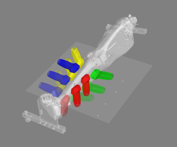
This script transforms the ultrasound positions and orientations of the desired segment to the image coordinate system of choice (CT or MRI) and displays in a mayavi window.
Make sure the subject directory follows the format outlined above and that all files are named according to the labeling specifications. You will also find a complete breakdown of the appropriate directory organization here.
- Modify directory, segment, imaging modality, and registration ID parameters that are located at the bottom of the script.
dir is the root directory of the subject (i.e. CMULTIS002-2)
segment is the segment that you are interested in viewing/transforming (Four options include: UpperArm, LowerArm, UpperLeg, and LowerLeg)
modality is the imaging modality that you would like the coordinates to be in (Either MRI or CT)
registration_id is the name of the registration directory to read registration marker STLs and send outputs to.
- Run the script.
- Outputs:
- Visualization of ultrasound locations during the experiment
Protocol - Save Data
This script transforms the ultrasound positions and orientations of the desired segment to the image coordinate system of choice (CT or MRI) and saves the data to an XML. Registration errors will also be saved as text files.
Make sure the subject directory follows the format outlined above and that all files are named according to the labeling specifications. You will also find a complete breakdown of the appropriate directory organization here.
- Modify directory, segment, imaging modality, and registration ID parameters that are located at the bottom of the script.
dir is the root directory of the subject (i.e. CMULTIS002-2)
segment is the segment that you are interested in viewing/transforming (Four options include: UpperArm, LowerArm, UpperLeg, and LowerLeg)
modality is the imaging modality that you would like the coordinates to be in (Either MRI or CT)
registration_id is the name of the registration directory to read registration marker STLs and send outputs to.
- Run the script.
- Outputs:
- XML document of probe tip positions in imaging coordinate system for each accepted trial corresponding to the subject, segment, and coordinate system chosen.
- Directory: Registration/"registration_id"/USPositions/"modality"/
- Naming convention: "registration id"_"Donor ID"_"Segment"_US_"modality".xml
- Example: R01_CMULTIS004-1_UL_US_CT.xml
- Text file of registration errors between digitized points and segmented spheres in specified image coordinate system.
- Directory: Registration/"registration_id"/QualityCheck/
- Naming convention: "registration id"_"Donor ID"_MQC_DG_"modality"_"segment".txt
- Example: R01_CMULTIS004-1_MQC_DG_CT_LA.txt
- XML document of probe tip positions in imaging coordinate system for each accepted trial corresponding to the subject, segment, and coordinate system chosen.
Dry Mock Registration Errors
CMULTIS006-1 (Leg) and CMULTIS012-1 (Leg) Comparison
- Sphere Placement
- Upper Segment (5 markers): Average = 0.37 mm, Maximum = 0.59 mm
- Lower Segment (5 markers): Average = 0.27 mm, Maximum = 0.40 mm
- Upper Segment (5 markers): Average = 0.24 mm, Maximum = 0.59 mm
- Lower Segment (5 markers): Average = 0.22 mm, Maximum = 0.50 mm
CMULTIS012-1 (Leg) and CMULTIS012-2 (Arm) Comparison
- Sphere Placement
- Upper Segment (3 markers): Average = 0.10 mm, Maximum = 0.14 mm
- Lower Segment (3 markers): Average = 0.08 mm, Maximum = 0.12 mm
- Upper Segment (3 markers): Average = 0.17 mm, Maximum = 0.27 mm
- Lower Segment (3 markers): Average = 0.11 mm, Maximum = 0.17 mm


