Contents
Target Outcome
Completed analysis of subject specific finite element model and comparison to in vitro experiments.
Protocols
Required Infrastructure
FEBio is a nonlinear implicit FE framework designed specifically for analysis in biomechanics and biophysics (Custom open source license; free for research use, licensing for commercial use is available, see http://www.febio.org).
Input
- Indentation and force data from in vitro experiments.
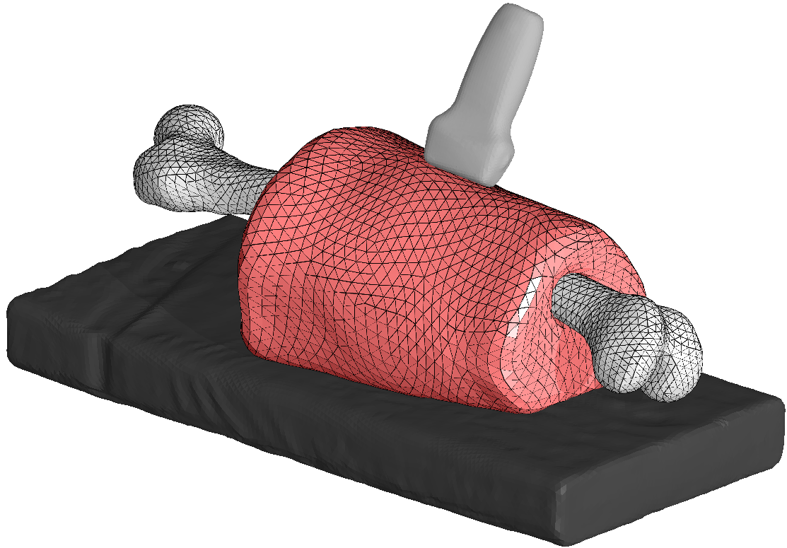
Completed leg or arm assembly, for more details, read below, or see Mesh Generation.
Procedures
Creation of Model Assembly
Creating the Surfaces
With the Image Segmentation of separate tissues, create a stl surface of the bone joined with the rest of the tissues layers. This was done by joining the individual layers into a single block, which can be done in Slicer by using the Editor. Within the Editor, the Change Label Effect makes one color of label change to another. This way the muscle, fat and skin can all be joined to create a "lumped" portion of the leg. However as it simplifies model generation later, joining the bone to the lumped flesh is also recommended. Use the Model Maker to generate the surface, and save the bone and the entire lumped model as separate stl files.
Remeshing the Surface
Using Mesh Lab, individually open the stls that were generated. The goal is to remesh the surface with triangles that are approximately similar in size at the desired mesh density. This process should be done for each of the stls.
First use Poisson Reconstruction. This does not produce the even triangle size that is desired, but the resulting surface can then be isoparameterized itself. Sometimes this reconstruction may produce undesirable results.Detailed instructions on Poisson Reconsctruction can be found here.
MeshLab's Iso Parameterization does an excellent job of remeshing, but it is very fickle and may crash MeshLab. Save before attempting. Detailed instructions on Iso Parameterizing can be found here.
When isoparmeterization has been completed, it is often useful to use Taubin Smoothing before saving the reconstructed mesh.
Cutting the Mesh
When the surface was created, the bone was included. This was to allow the bone surface to be cut from the flesh surface, ensuring a perfect fit. If this was not done the remeshing and smoothing steps will have created a small, but noticeable amount of overlap. Cutting the flesh stl with the bone stl will prevent this overlap. This is accomplished by using the Python script CutStlWithStl.py found here. In addition to creating a perfect fit between the surfaces, this also makes the node coordinates of one surface identical to the other, which seems to improve the simulation models enforcement of boundary constraints between these surfaces.
Placement of the ultrasound probe
The probe Stls can be found at https://simtk.org/svn/multis/app/Registration/Probe%20STLS/
Once you have a local copy you can use the script initial_probe_positions.py found here.
In addition to the stl you will need the registration xml for the model you are using, it will be named something like CMULTIS00X-1_UL_US_CT.xml
Model Assembly
Once both the cut lumped flesh stl and the transformed ultrasound probe stl have been made, it is time to make the Connectivity xml document that the model assembly script will use to prepare the model. It should look something like this.
<Assembly>
  <Bone>
    <file>Femur.stl</file>
    <material>rigid</material>
    <Tie>
      <Flesh multiplier="0.7"/>
    </Tie>
  </Bone>
  <Flesh>
    <file>Lumped.stl</file>
    <material>elastic</material>
    <Tie>
      <Bone multiplier="0.8"/>
    </Tie>
    <Contact>
      <Probe multiplier="1.2"/>
    </Contact>
  </Flesh>
  <Probe>
    <file>Probe_transformed.stl</file>
    <material>rigid</material>
    <Contact>
      <Flesh multiplier="1.5"/>
    </Contact>
  </Probe>
</Assembly>
In-Situ Strain
The geometry of the limb is taken from medical imaging and obviously gravity was acting on the limb while it was being measured. What may not be obvious, is how to get this force applied in the model without further deformation.
Within FeBio we propose to use the prestrain plugin. This plugin allows the load of gravity to be applied, without updating the geometry, but instead applying strains to equilibrate the internal forces. Some changes to the input (.feb) file to achieve this:
Change the material definitions:
<material id="1" type="neo-Hookean">
        <density>1e-9</density>
        <E>1000.0</E>
        <v>0.45</v>
</material>
becomes:
<material id="1" type="prestrain elastic">
        <elastic type="neo-Hookean">
                <density>1e-9</density>
                <E>1000</E>
                <v>0.45</v>
        </elastic>
</material>
It is usually better to ramp of the loading. Hold the geometry fixed and calculating the prestraining itself is accomplished by:
<Constraints>
        <constraint type="prestrain">
                <tolerance>0.01</tolerance>
                <update>1</update>
        </constraint>
</Constraints>
After the prestraining has occurred the an additional Step can be added to accomplish the goal of the simulation.
Output
- Thicknesses of layered tissues
- Forces

