Contents
For discussions on establishing these specifications, please refer to /Discussion.
Target Outcome
- Demographic documentation (age, gender, ethnicity, race, activity level)
- Anthropometric measurements (body mass, height, extremity lengths and circumferences)
- Ultrasound images at unloaded state to extract tissue thickness for various extremity locations
- Ultrasound imaging during indentation to extract tissue thickness for various extremity locations
- Loads applied by the probe on the segment during unloaded state and indentation
Prerequisites
Infrastructure
Protocols
Procedures
Prior to subject arrival
- Supplies: ultrasound gel, consent forms, pens, washable markers, cloth tape measure, flashdrive, bed sheet, pillow, pillowcase, wash cloths, gel disposal cup with tongue depressor
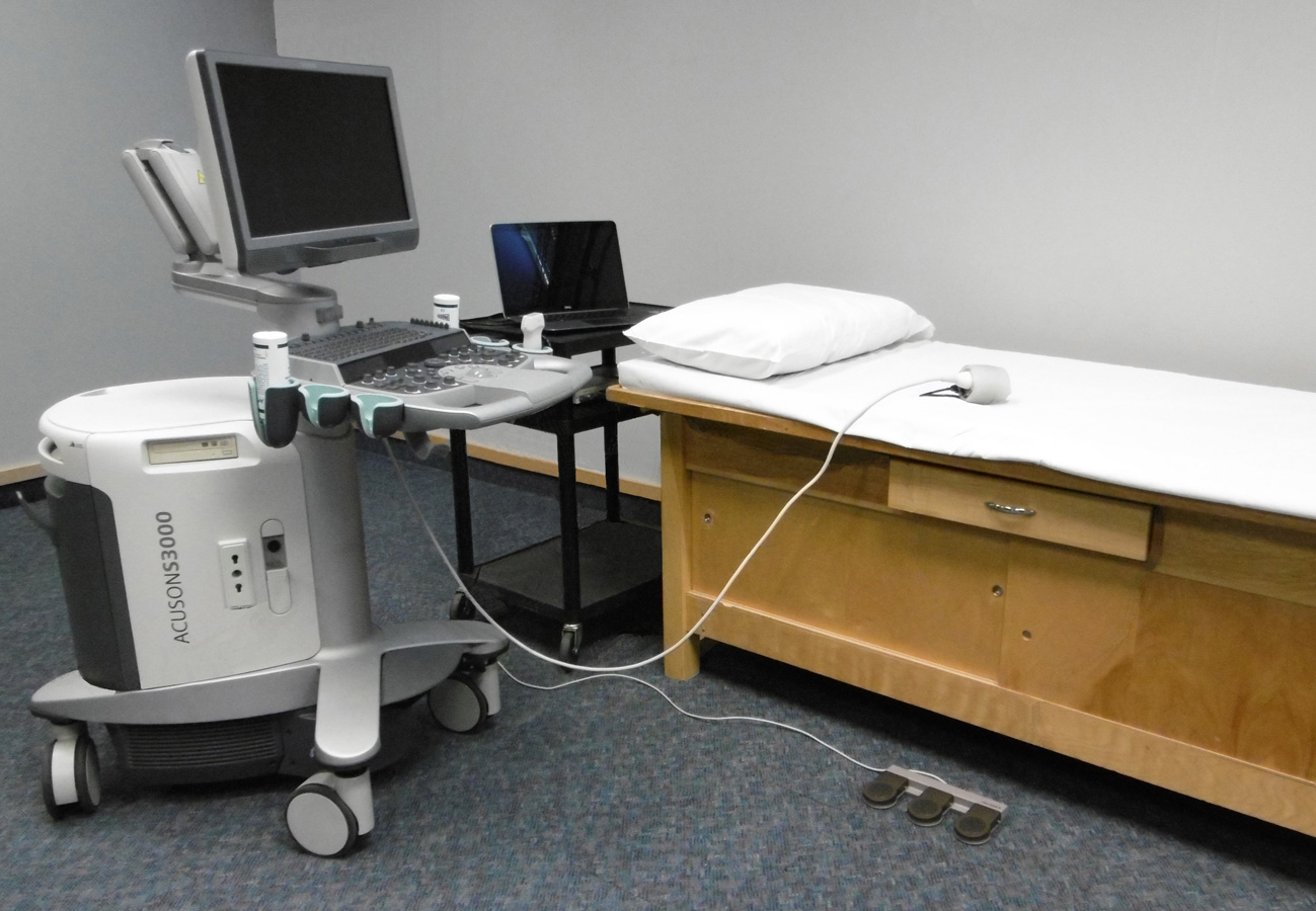
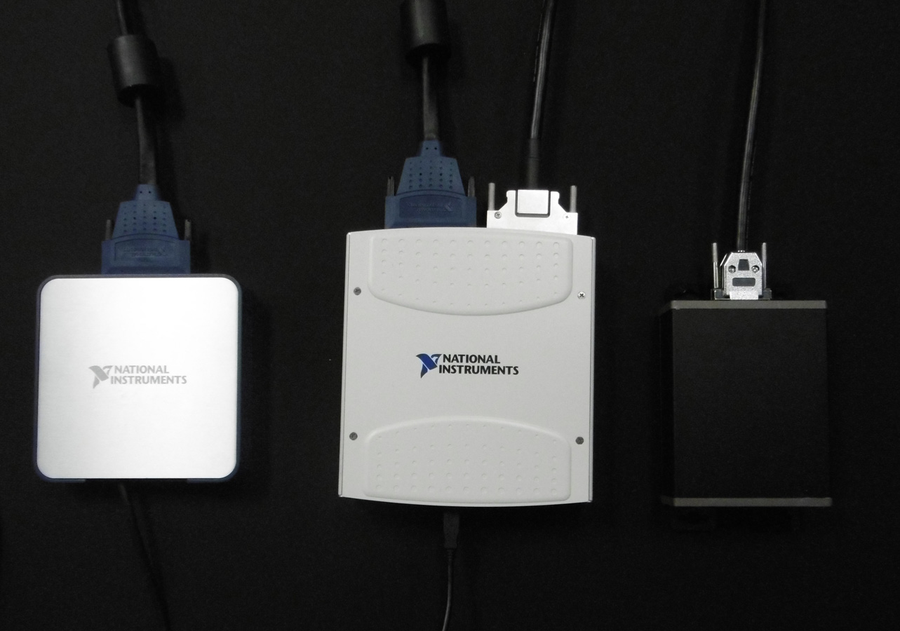
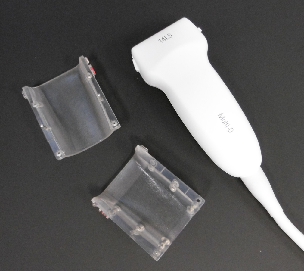
- Equipment: Ultrasound system with foot-switch, 14L5 probe, 9L4 probe, clam shells for each probe, casing unit with load cell and orientation sensors, load-transducer computer with wireless remote, black ATI unit, blue DAQ unit, beige DAQ unit, computer cart, power strip, scale for body mass and height measurements, exam table with surgical mat, and a projector
- Examination table will be placed in the middle of the lab near the floor outlet.
- Place a clean bed sheet on the surgical mat of the examination table and a clean pillowcase on the pillow.
- Set-up LInUS
- Plug ultrasound system, power strip, and computer cart power strip into the floor outlet
- Plug computer and beige DAQ unit into the computer cart power strip. The computer will be placed on the top shelf of the computer cart while the beige DAQ unit and the blue DAQ units are located on the second shelf of the computer cart.
- Plug black ATI unit into the power strip. The power strip will be located under the examination table and the black unit will be placed within the drawer of the examination table.
- Connect the orientation sensor (attached to the load-transducer casing) to the computer via the USB
- Connect the beige DAQ unit to the computer via the USB
- Connect the blue DAQ unit and the black ATI unit to the beige DAQ unit
- Connect the USB for the wireless remote to the computer
- Plug the phone jack connector from the blue DAQ into the Auxilliary 1 ECG input on the ultrasound system
- Plug the load-transducer sensor into the black ATI unit
- Plug the foot-switch into the ultrasound system via the USB
- Turn on the power strips, the load-transducer computer, and the wireless remote
- Connect the project to the computer. The project will display the computer screen onto the far wall for better viewing by the investigator.
- Log into the load-transducer computer using your personalized Cleveland Clinic username and password
Press the Ultrasound Power On/Off Button (
 ) on the upper left side of the control panel to turn the ultrasound system on. A green blinking light indicates the power is on. It will take 2-3 minutes for the system to boot-up.
 - Connect the 14L5 and the 9L4 transducers to the ultrasound system. To connect a transducer to the system, insert the transducer connector into one of the active transducer ports with the cable up. Be sure it is placed all the way into the port and then rotate the transducer lock handle clockwise to lock the transducer connector into place.
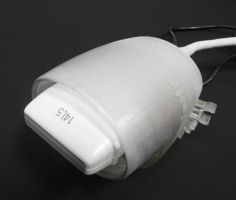
- Connect the clam shells to the probes. Insert the 14L5 probe with clam shell into the casing unit.
- Secure the wires for the ultrasound probe, load-cell, and orientation sensor within their respective clamps attached to the casing unit.
- Verify the blue line indicating the pulse train is visible on the ultrasound screen. If not visible, unplug and plug back in the phone jack connector into the ultrasound system.


Subject arrival/initial contact
- Review the consent document with the subject. All questions asked by the subject will be addressed. The consent document will be signed by the subject and by the investigator obtaining consent. A signed copy of the consent form will be given to the subject with the original filed with the IRB binder.
- Show the subject the changing room and have them change into shorts and t-shirt. Remind them to use the restroom if needed.
- Setting up the load-transducer computer:
- Double click on "MULTiS collection" icon in upper right corner of load-transducer computer screen.
- Begin the program by clicking the arrow in the top left corner of the window (below Edit).
- Click 'Default' when asked if you want to load the default configurations or the most recent.
- Click 'New Subject' when asked if you would like to test a new subject or retest a previously tested subject. Note the Subject ID in the upper left corner of the new window. This number will need to be entered into the ultrasound computer.
- Measure the subject's height and body mass on the scale in the laboratory area. This data will be entered into the force transducer computer under the Subject Data tab.
Ask the subject the demographic and activity level (ActivityLevel.pdf) questions and record the answers on the force transducer computer. The demographics questions include age, gender, ethnicity, and race. The activity level refers to how active the subject is during normal, daily activities.
- Click 'Enter' at the bottom of the window.
- Configuring the load cell:
- Click 'Configure Sensors' in the upper left corner of the window.
- Verify that the Ultrasound Probe is for the 14L5 and that the Experiment Run Duration is 8 seconds
- Click 'Stream' and verify that data is being collected. Only the 6-DOF Load data should be displayed. Stop the display by clicking 'Stream'
- Click 'Establish Orientation'
- Orient the ultrasound probe in the positive (or negative) direction for one of the axis and click 'Capture'. Select the next 'Position Selected for Capture' and move the probe into the negative (or positive) direction along the same axis and click 'Capture'. Continue until all 6 degrees of freedom have been recorded.
- Under 'Gravity Compensation Parameters', click the division sign to the left of 'Calculate All'. Once the calculations are complete, close the window by clicking the X in the upper right corner of the window.
- Click 'Stream' to verify that the sensor values are near zero. If not, repeat the configuration process.
- Setting up the ultrasound computer:
Click the Patient Registration icon on toolbar (
 ) in the upper left corner of the ultrasound screen. Using the Short Form, enter the Subject ID for Last Name and for Patient ID. Use the drop-down menu to select “MSK” for Study type and “14L5” for Transducer. Click OK to start the exam.
- Change study type to MULTIS and Duration (under Protocol) to 10 seconds.
- Again, verify the blue line indicating the pulse train is visible on the ultrasound screen. If not visible, unplug and plug back in the phone jack connector into the ultrasound system.
Subject preparation for the arm
- Instruct the subject to lie supine on examination table with their right side toward the investigator. All testing will be conducted on the right side of the body. All marks on the body will be made using a washable marker.
- Mark the location of the following landmarks with a dot (●):
- ulnar styloid process
- humeral lateral epicondyle
- inferior lateral acromion
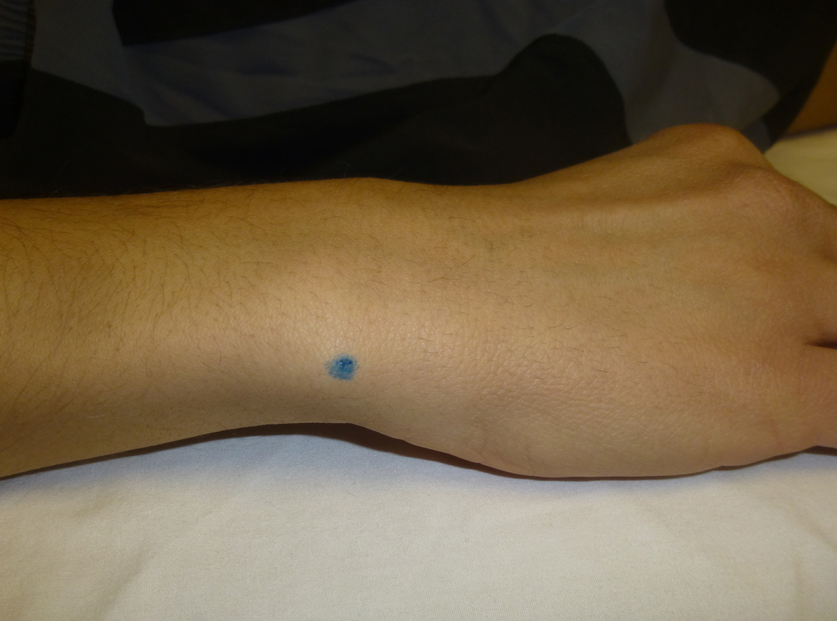
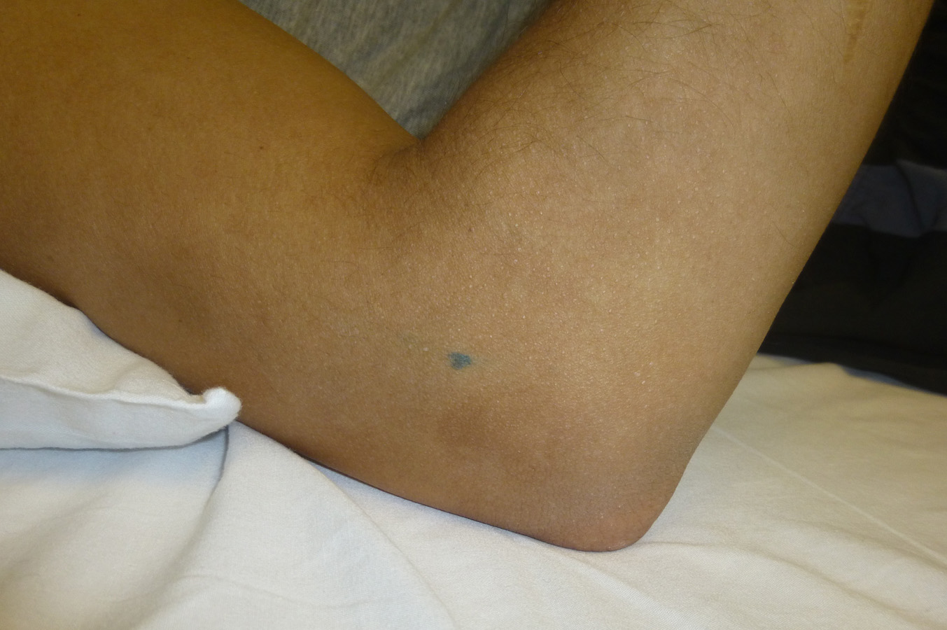
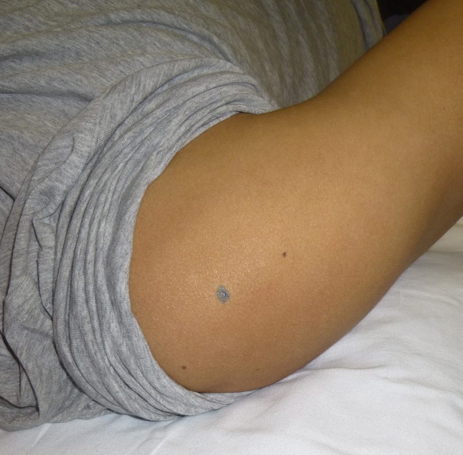
- Draw the circumference around the regions of the upper and lower arm:
- distal shaft of the humerus
- distal axillary
- the midpoint between the distal shaft of the humerus and the distal axillary
- distal shaft of ulna-radius
- proximal shaft of ulna-radius
- the midpoint between the distal shaft of ulna-radius and the proximal shaft of ulna-radius

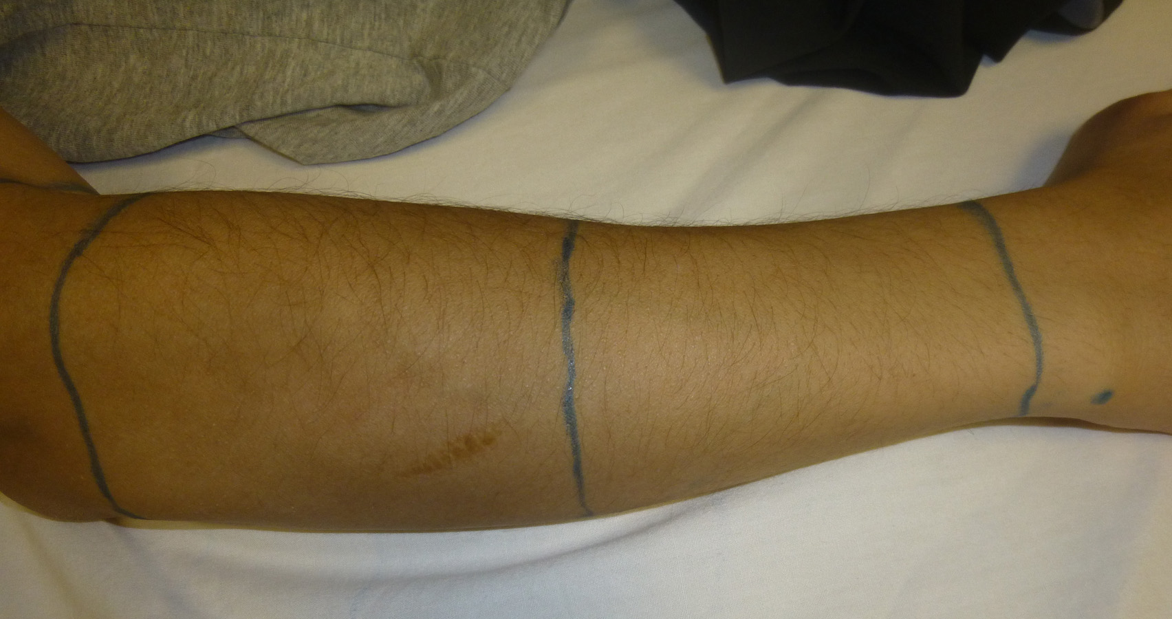
- Place the right arm in anatomical position (palms up) and abducted away from the body about 45 degrees.
- Draw a line along the anterior radius from the distal shaft of the ulna-radius circumference through the midpoint circumference to the proximal shaft of the ulna-radius circumference
- Repeat these lines along the lateral radius and along the medial ulna.
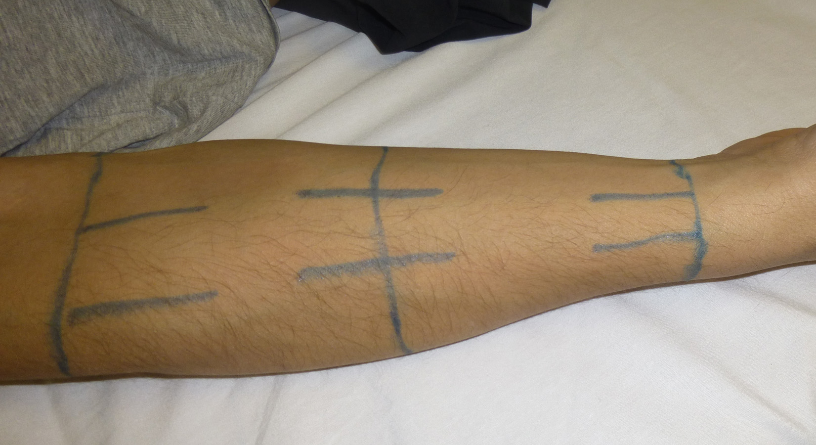

- Draw a line along the anterior humerus from the distal shaft of the humerus circumference through the midpoint circumference to the distal axillary circumference
- Repeat these lines along the lateral humerus and along the medial humerus.
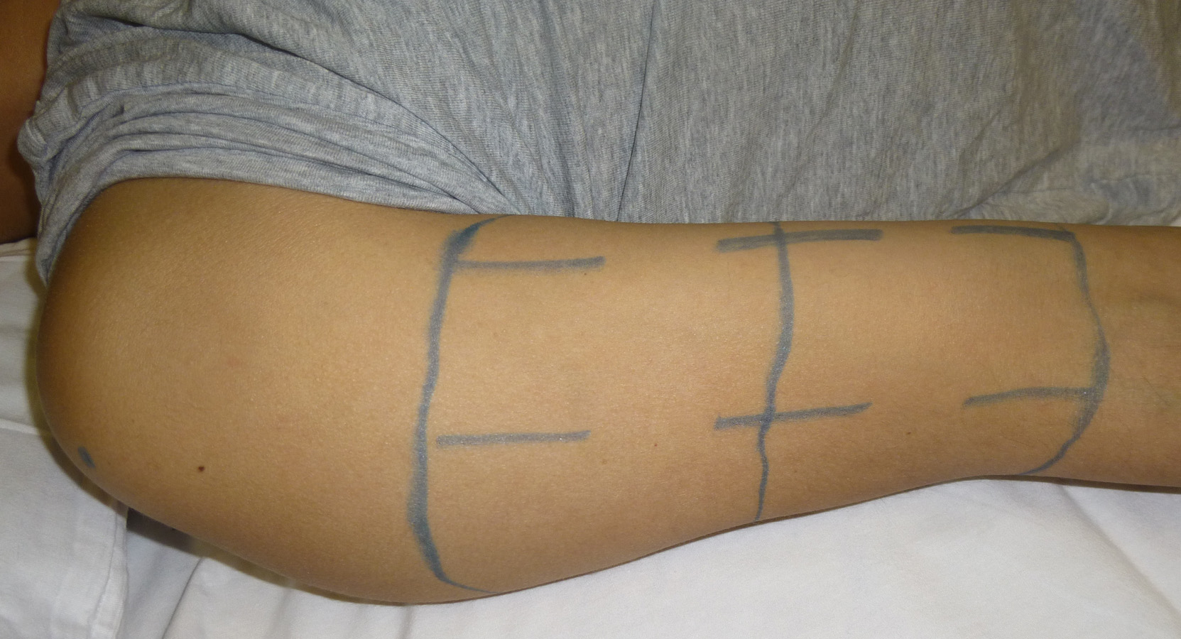

- With the subject in the prone position, draw a line along the posterior radius from the distal shaft of the ulna-radius circumference through the midpoint circumference to the proximal shaft of the ulna-radius circumference
- Draw a line along the posterior humerus from the distal shaft of the humerus circumference through the midpoint circumference to the distal axillary circumference
Subject preparation for the leg
- With the subject lying supine and in anatomical position, mark the location of the following landmarks with a dot (●):
- greater trochanter
- tibial plateau
- lateral malleolus
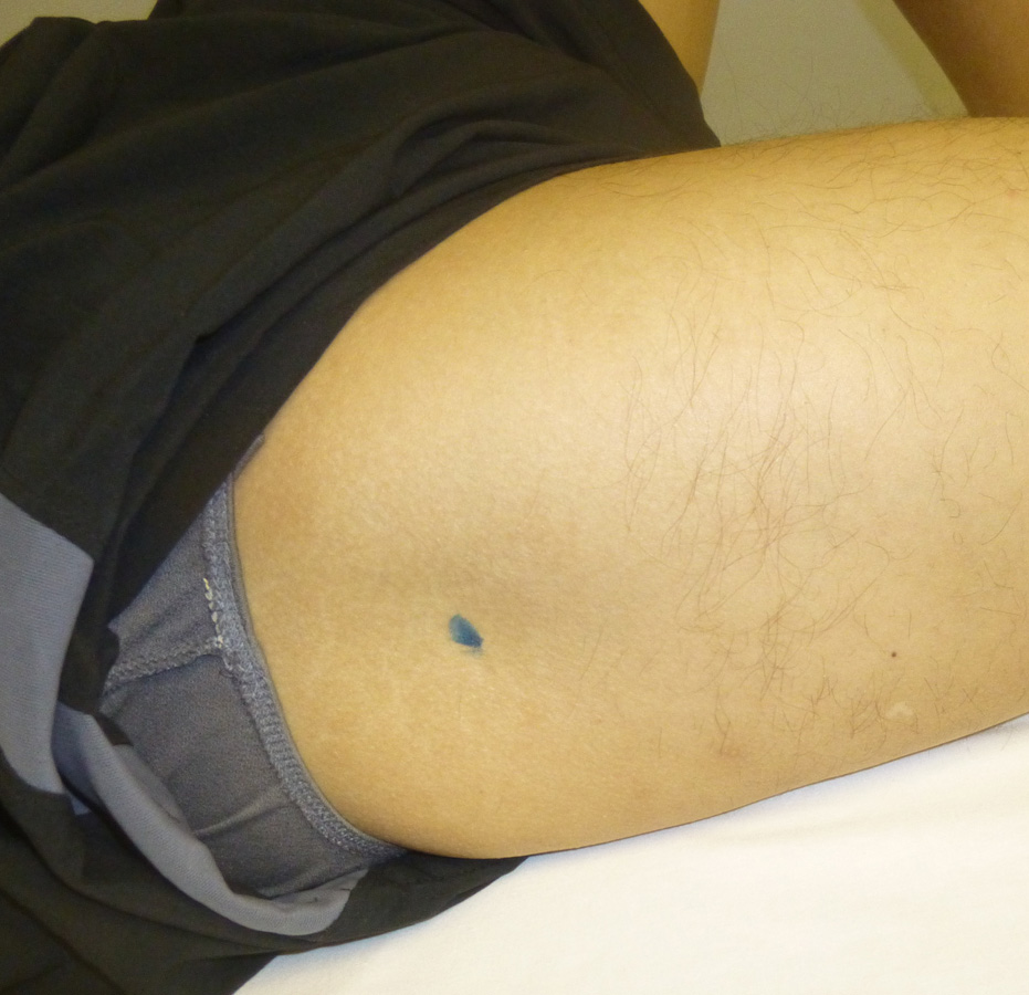


- Draw the circumference around the regions of the lower and upper leg:
- distal shaft of the tibia
- distal tibial tuberosity
- the midpoint between the distal shaft of the tibia and the distal tibial tuberosity
- distal shaft of the femur
- top of the inner thigh
- the midpoint between the distal shaft of the femur and the top of the inner thigh

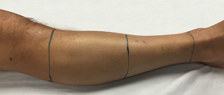
- Place the right leg in anatomical position with the ankle joint at ~90 degrees
- Draw a line along the lateral side of the anterior tibia from the distal shaft of the tibia circumference through the midpoint circumference to the distal tibial tuberosity circumference. Imaging will be examining the distance between the skin and the fibula.
- Repeat these lines along the lateral fibula and along the medial fibula.

- Draw a line along the anterior femur from the distal shaft of the femur circumference through the midpoint circumference to the top of inner thigh circumference
- Repeat these lines along the lateral femur and along the medial femur.
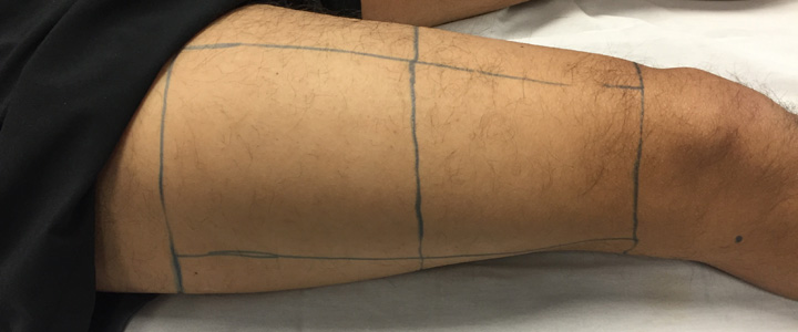
- With the subject in the prone position, draw a line along the posterior tibia from the distal shaft of the tibia circumference through the midpoint circumference to the distal tibial tuberosity circumference
- Draw a line along the posterior femur from the distal shaft of the femur circumference through the midpoint circumference to the top of inner thigh circumference
Record circumferences and landmark/circumference locations
- The following measurements will be recorded into the force transducer computer under the Measurement tab.
- Record the length (cm) of each circumference.
- Record the distance(cm) from the inferior lateral acromion landmark to the following:
- humeral lateral epicondyle landmark
- distal shaft of the humerus circumference
- upper arm midpoint circumference
- distal axillary circumference
- Record the distance (cm) from the humeral lateral epicondyle landmark to the following:
- ulnar styloid process landmark
- distal shaft of the ulna-radius circumference
- lower arm midpoint circumference
- proximal shaft of the ulna-radius circumference
- Record the distance (cm) from the greater trochanter landmark to the following:
- tibial plateau landmark
- distal shaft of the femur circumference
- upper leg midpoint circumference
- top of inner thigh circumference
- Record the distance (cm) from the tibial plateau landmark to the following:
- lateral malleolus landmark
- distal shaft of the tibia circumference
- lower leg midpoint circumference
- distal tibial tuberosity circumference
Ultrasound with 14L5 probe
- The "vertical" marking on the probe will always be directed superior to the "horizontal" marking on the probe.
- Throughout testing, verify that the arm and leg remain in an anatomical position throughout scanning of those regions. The arm should be abducted away from the body about 45 degrees. For the leg, the ankle joint should be at ~90 degrees. To access the medial region of the leg, the contralateral leg can be abducted away from the midline of the body.
- Throughout testing, for the anterior regions, collect the indentation trial at the central location immediately following the ultrasound scan at that location.
- Scanning can be performed in any order. We will begin with the anterior upper arm and perform all scan at the locations for which the 14L5 is appropriate (lower arm, anterior/lateral/medial upper arm, as well as the distal lower leg).
- Place ultrasound gel along the region to be scanned and place the probe along one of the lines.
Adjust Gain, Depth, and Focus to obtain the best image from skin to bone. Adjust the gain by using the TEQ button (
 ) which will optimize the brightness. The middle footswitch pedal has been assigned as the TEQ button. Adjust the focus so that it is in the middle of the region of interest (skin to bone). Adjust the depth so that the entire image will fill the screen.
 - Press foot switch (left or right pedal) to acquire the ultrasound image and immediately press the collect button on the wireless remote to collect the load-transducer data. The ultrasound data will be saved automatically and will be displayed in the thumbnail panel at the right side of the screen. On the load-transducer computer monitor, review the maximum forces occurring during the trial and if they are at acceptable levels, click the accept button on the wireless remote to accept the trial. If the trial needs to be repeated, click reject.
- If the distance from the skin to the bone cannot be seen clearly using the 14L5 probe (due to the depth of the muscle), skip that location until all possible 14L5 locations are acquired.
- Gel can be wiped off of the subject following each successful scan or as a region is completed. Use the tongue depressor to scrape off any excess gel and then use the washcloth to wipe off any remaining residue.
Ultrasound with 9L4 probe for remaining locations
- Transfer the load cell casing to the 9L4 probe.
- Switch the active transducer port on the ultrasound computer by clicking Transducer on the top left of the screen and choose the appropriate transducer. Yuo will need to reset the duration to 10 seconds.
- Again, verify the blue line indicating the pulse train is visible on the ultrasound screen. If not visible, unplug and plug back in the phone jack connector into the ultrasound system.
- Re-configure the load cell - details previously listed.
- Scan any remaining locations using the 9L4 probe.
- Once all 48 ultrasound scans and 8 indentation trials have been collected, the data collection is complete.
Ending the examination
- End the exam by pressing the Report button and click on End Exam.
- Clean all ultrasound gel and pen markings from the subject.
- Inform the subject that they will be receiving a check in the mail for their participation.
- Inform the subject that the study has concluded and they are free to leave.
- Transfer data (see instruction below).
Press the Power On/Off Button (
 ) on the upper left side of the control panel to turn the system off. Click System Shutdown if no additional exams will be performed for the day.
 - Take the used washcloths, bedsheet, and pillowcase to a soiled linen location for laundering.
Data transfer
- On the load cell computer, zip the raw data for this subject. The folder can be found in c:\MULTIS data.
The zipped folder can be transferred to MIDAS (http://cobicore.lerner.ccf.org/midas/community/7) using the secure wireless connection. The data will be saved in the path /Private. The folder may be unzipped, but leave original zipped folder.
- This data will be transferred to the 'MULTIS_trials' folder on the linux computer located in the lab for file association.
- On the ultrasound computer, transfer the ultrasound data in DICOM Format by inserting a USB stick into the ultrasound machine. This USB stick should have a directory named "EXPORT" in the root of the USB drive.
- Press Patient Browser (F2) and select the exam to be transferred.
- Click on the Transfer drop-down menu and select Export to offline.
- Select Drive: E:\Export and Format: DICOM
When the transfer is complete, insert the USB stick into the load cell computer and transfer to the desktop. Zip the ultrasound data and upload the zipped folder to the Ultrasound directory for this subject (http://cobicore.lerner.ccf.org/midas/community/7 and saved in the path /Private).
- This data will also be transferred to the 'MULTIS_trials' folder on the linux computer located in the lab for file association.
- After 2 weeks, the data can be removed from the ultrasound system.
Output
All raw data can be found at http://cobicore.lerner.ccf.org/midas/community/7
- Ultrasound images in DICOM format are located in the path /Private/MULTISXXX-1/Ultrasound, where XXX is the unique subject identifier (i.e., 001, 002, 003, etc.)
- Configuration and data directories are located in the path /Private/MULTISXXX-1/, where XXX is the unique subject identifier (i.e., 001, 002, 003, etc.)
Next step: DataAnalysis

