Contents
- Validity of Using Ultrasound to Measure Muscle Thickness
- Probe Selection
- Subject positioning
- Length and circumference measurements
- Considerations after mock-up testing - Session I
- Considerations after mock-up testing - Session II
- Considerations after mock-up testing - Session III
- Considerations after mock-up testing - Session IV
- Considerations after mock-up testing - Session V
- Considerations after mock-up testing - Session VI
- Considerations after mock-up testing - Session VII
- Settings
This is the discussion page of Specifications/InVivoTesting
Validity of Using Ultrasound to Measure Muscle Thickness
Pretorius A, Keating JL. Validity of real time ultrasound for measuring skeletal muscle size. Physical Therapy Reviews 13:415-426, 2008.
O'Sullivan C, Meaney J, Boyle G, Gormley J, Stokes M. The validity of rehabilitative ultrasound imaging for measurement of trapezius muscle thickness. Manual Therapy. 14:572-578, 2009. http://www.ncbi.nlm.nih.gov/pubmed/19264532
Mendis MD, Wilson SJ, Stanton W, Hides JA. Validity of real-time ultrasound imaging to measure anterior hip muscle size: a comparison with magnetic resonance imaging. Journal of Orthopedic and Sports Physical Therapy 40:577-581, 2010. http://www.ncbi.nlm.nih.gov/pubmed/20479536
Worsley PR, Kitsell F, Samuel D, Stokes M. Validity of measuring distal vastus medialis muscle using rehabilitative ultrasound imaging versus magneticresonance imaging. Manual Therapy 19:259-263, 2014. http://www.ncbi.nlm.nih.gov/pubmed/24582328
Belavý DL, Armbrecht G, Felsenberg D. Real-time ultrasound measures of lumbar erector spinae and multifidus: reliability and comparison to magnetic resonance imaging. Physiological Measurement. 36:2285-9922, 2015. http://www.ncbi.nlm.nih.gov/pubmed/26450474
Abstracts: ../Validity.pdf
Probe Selection
The Siemens Acuson S3000 Ultrasound system will be used for the in vivo portion of this study. Up to three probes can be attached to the ultrasound system concurrently. There are 5 ultrasound probes that are currently available to us:
9L4 (4-9 MHz) – linear array, musculoskeletal applications
14L5 (5-14 MHz) – linear array, musculoskeletal applications
18L6 (5.5-18 MHz) – linear array, musculoskeletal applications
6C1HD (1.5-6 MHz) – curvilinear array
4V1c (1-4.5 MHz) – linear array
Based on the regions of the body that will be examined and in discussions with another investigator familiar with each of the probes, the 4V1c was not recommended for this application. Additionally, the 14L5 and the 18L6 probes were deemed to be of similar quality. Because different probes may be better for scanning different regions of the body, we will conduct a pilot test to determine which probe provides the most useful images. Probes 9L4 and 14L5 will be used on one of the investigators at each of the 48 testing locations of the body (14L5 was chosen over the 18L6 due to the similarity in the handle shape to the 9L4 which may become an advantage when developing the attachment for the force transducer). To further ensure us that the most appropriate probe is being used at each location, the 6C1HD probe will be used at the upper thigh locations and the 18L6 will be used at the lower arm locations. All images will be compared to determine the optimum probe to be used at each location. Siemens has loaned us a 3D probe (7CF2 – 2-7 MHz) to evaluate if it would be useful for this project. After evaluating the 3D probe, it was deemed not useful for this application and was returned to Siemens.
Conclusion: We have chosen to use the 14L5 and the 9L4. The 14L5 will be used when depth to the bone is less than 6 cm. For most subjects, this will be for the lower arm, a portion of the upper arm, and the anterior lower leg. The 9L4 will be used for all other regions. Ideally, we will only switch probes once. We will begin with the 14L5 and then change to the 9L4. This will require the subject to rotate between supine to prone a few times.
Subject positioning
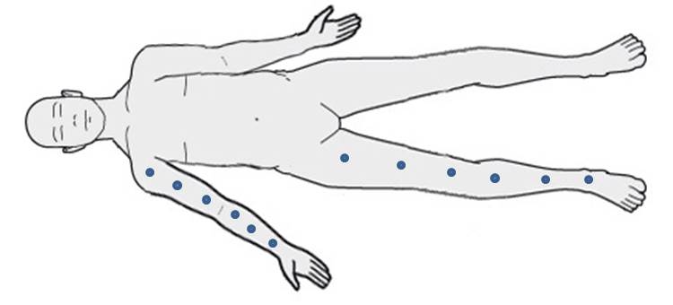
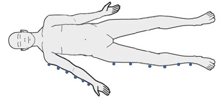
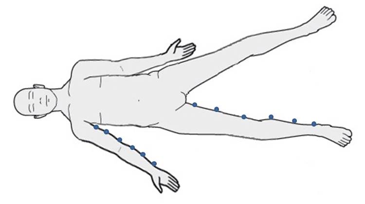
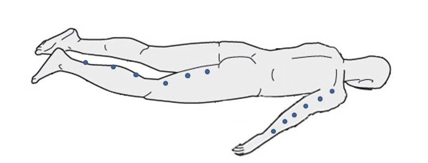
Since the objective of this study is to establish models for the mechanics of multi-layer tissue structures of the limbs to allow reliable virtual surgical simulations, we decided that the positioning of the subject should be based on surgical positioning. Ultrasound images will be made with the subjects lying on the examination table (versus being in a standing or sitting position). Per discussions with some surgeons, patients in the operating room would be placed supine for anterior or lateral approach or prone for posterior approach. For medial approach, the leg would be positioned in a low lithotomy with the hip externally rotated and the knee flexed. For a medial approach of the upper extremity, the arm would be extended straight at the shoulder with someone holding the arm up or by having a traction device hold the arm. Per discussions with radiologist, there is no standard method for positioning the patient during scanning, so suggested that the most reliable approach would be to keep the patient in the anatomical position with the hands facing forward and the feet straight out in front. For the medial approach, they recommended leg or arm abduction away from the anatomical position without rotation of the extremity. To standardize all positions and maintain consistency between subjects, we have elected to place all subjects supine, in anatomical position, with the arm abducted 45 degrees. This positioning will be used for anterior and lateral images. For medial images, the contralateral leg will also be abducted to access the medial aspect of the upper leg. This will maintain a standardized position for the scanning leg. For posterior images, the subject will maintain the anatomical position with the arm abducted 45 degrees, but in a prone position.
- Anterior
- Lateral
- Medial (contralateral leg is abducted to access medial thigh)
- Posterior
Length and circumference measurements
Considerations after mock-up testing - Session I
The whole testing including anthropometric measurements and ultrasound imaging for thickness measurements and indentation should be completed in < 2 hours.
- Location of circumference in relation to anatomical landmarks should be measured.
- Brightness/contrast setting of ultrasound imaging should be standardized.
- Level of zooming in the ultrasound images should be standardized.
- The order of imaging locations should minimize number of ultrasound probe swaps.
- The order of imaging can prioritize locations on the arm first then the leg, and subject laying on back first than on stomach. Imaging during indentation can immediately follow thickness imaging at the same location.
- An inventory of equipment and list of supplies need to be kept, ideally on this page.
- The surface mat on which the subjects will lay down, should be standardized. Ideally it should be a surgical mat with known material properties.
- Target bones for lower leg and lower arm based on imaging location should be detailed.
- The longitudinal orientation of the ultrasound probe during imaging should be standardized, i.e., positioning of probe horizontal mark on the distal side.
A procedure to transfer ultrasound images from the system to a data management infrastructure should be documented. It is anticipated that data from each subject will be > 1 GB.
Considerations after mock-up testing - Session II
Only the arm was tested, preparation, assembly of setup (including force measurements) and testing took < 2.5 hours.
- Data collection software:
- In the data collection interface provide a sensor check button and display to ensure everything is working before experiments start.
- Software measurements should be SI, no inches centimeters.
- Software needs to have a duration setting.
- Auditory feedback to notify end of force transducer data collection will be helpful.
- All central locations for indentation should be listed in the software.
- An issue was noted when the software tried to run a trial that was already accepted.
- Connection to orientation sensor dropped.
- A feature to overwrite to reject a previously accepted trial will be helpful.
- A probe selection will be useful where the selection can be saved with trial data.
- Ultrasound system:
- Enter subject id in force measurement system and use the same subject id for ultrasound.
- Foot switch should allow stopping of data collection automatically.
- When probe was switched, ultrasound system EKG needed to be plugged out in again and time duration, and the beat needed to be reset.
- Ultrasound probe - force transducer assembly:
- Orientation of the clamshell relative to probe needs to be marked on the probe.
- Design changes on clamshell to allow guidance during tightening.
- Clamshell design should have a stopper at the marks.
- Ultrasound cable holder is too big.
- Zip tie / Velcro cables.
- Transfer cable holders to the other side.
- The probe assembly is heavy. Tammy is resting it on the region rather than pulling up.
- Use shorter studs (with allen wrench) to assemble the handle (to prevent sticking thumbscrews).
- General setup:
- Placement of ultrasound cart and force measurements cart needs thinking.
- Specifications may need to include a step to check if everything works.
- Moderately active sounds active.
- It will be helpful to remember doing indentation after unloaded imaging.
- Taring and calibration should be performed in case an issue rises.
Considerations after mock-up testing - Session III
- Conducted an abridged session to test the software.
- Data collection software:
- Create a log file for tested subjects to increment subject number in case subject folders do not exist any more.
- Change activity level descriptors in subject configuration interface.
- In sensor configuration, mass should be kg not N.
- In calibration panel, a clear button may be useful to remove collected calibration data for recalibration of gravity compensation.
- Weight the probe (9L4) and shell to confirm their mass. Calibration says it is 0.24 kg.
- Automate calibration file name, e.g. Subject id _ probe ID _ trial ID (auto increment).
- For streaming data, units should be reported in the legend.
- For streaming data, checkboxes may need to be rearranged to select and plot groups of channels.
- System crashes when streaming and calibrating are active at the same time.
- Calibration errors seem high, 1.2 N for 2.5 N weight.
- Configuration window disappears after rejecting a trial, it may be a remote mouse issue. There are other issues related to the clicker that need to be resolved.
- LabVIEW code need to be in the repository.
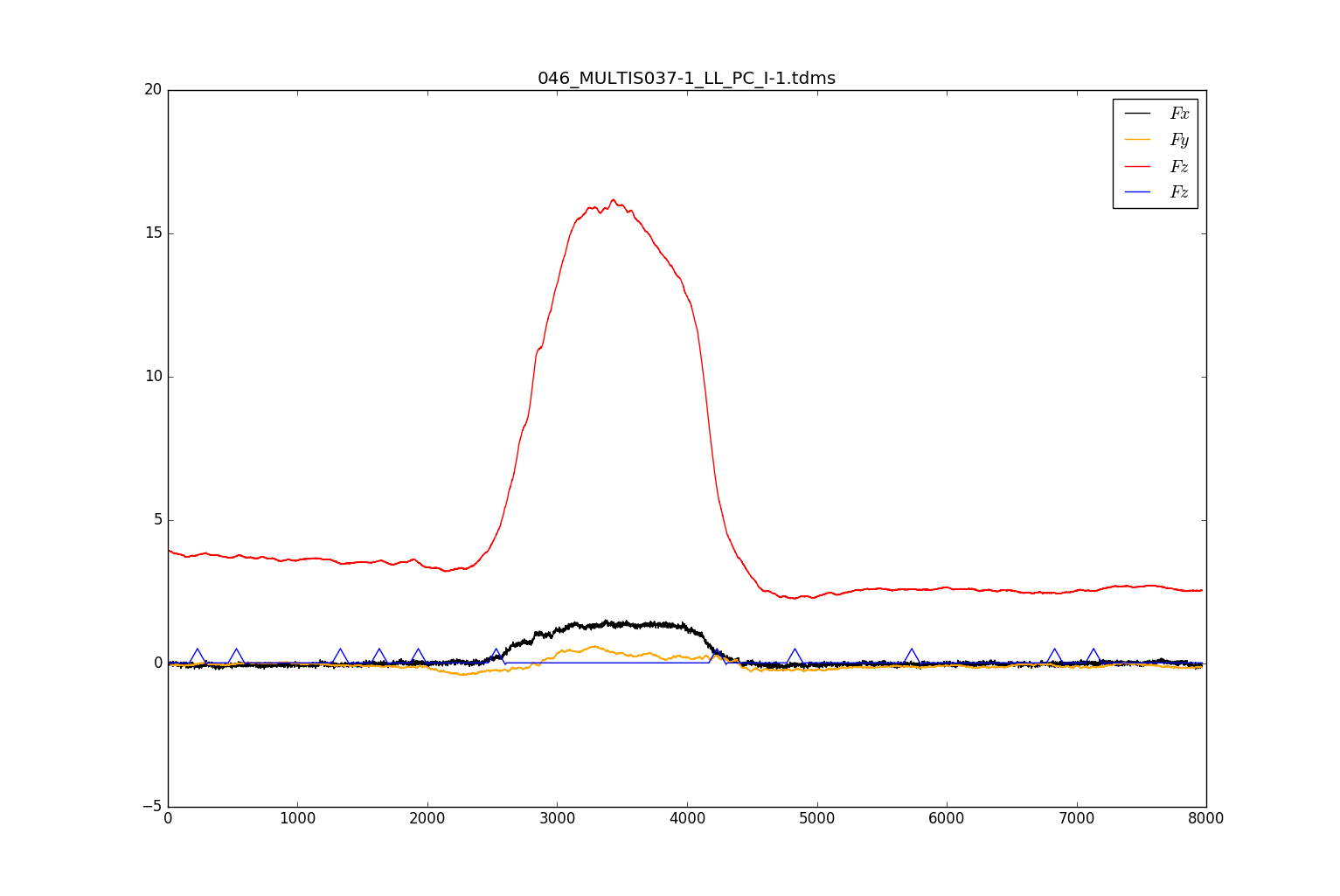
- First data point collected for forces with the force transducer during imaging is a spike, this affects max shear and normal force reporting.
- Is it possible to get the testing location list from a file, therefore allowing the user to re-order it if desired?
- Ultrasound system:
- The labels on the image can be removed; need to be discussed.
- A foot switch should be ordered. One borrowed from the Li Laboratory works to start ultrasound imaging and let it stop automatically.
- Ultrasound probe - force transducer assembly:
- Transformation matrix for ultrasound probe 14L5 need to be obtained to incorporate in the data collection software.
- A new clip for ultrasound probe cable is needed.
- General setup:
- It may not be possible to target fibula from distal medial lower leg location. Yet, when possible, record data by targeting at it.
- Tammy wanted to streamline data collection by pre-applying ultrasound gel and going over regions quickly. Yet, she may need to wait for synchronization signal to clear up from the imaging screen.
Considerations after mock-up testing - Session IV
- Set ultrasound probe 14L5 to default (Tara)
- Change weight to mass in subject specifications
- Alter program so that when measurement is recorded i.e. circumference, operator can press "Enter" or "Tab" to switch to next input box more easily.
- Remember reading glasses (Tammy)
- Change duration default to 8 seconds
- Fix ultrasound cable attachment. Needs longer screw and needs to be glued in place to prevent rotation. Also may add another ultrasound cable attachment to further stabilize.
- Change stream button to default to just 6 DOF load
- Evaluate weight compensation due to cables
- When clicking on positions and changing ultrasound probe, check collection state
- The collected and accepted did not register
- Re-ordering the collection order
- 4 trials on lower leg - see if they are in data files
Considerations after mock-up testing - Session V
Ahmet & Tyler test Multis data collection software
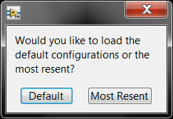
- Change "Resent" to "Recent"
- Separate units from labels
- after further consideration this may not be necessary
- Software freeze on exit
- fixed
- note for Tammy: In order to change display i.e. add load cell Fx to plot, must do so while collecting data, not before or after. Then, added load cell direction will continue for each trial until changed.
- Lower arm and lower leg measurement data swap after stopping, then resuming testing
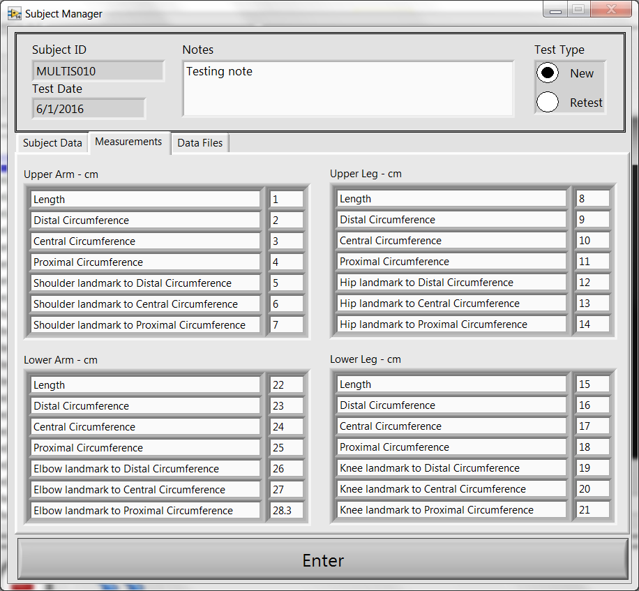
- Example of latest xml
- User Interface found on the following page
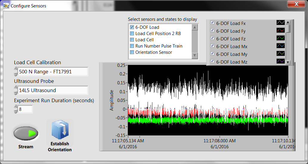
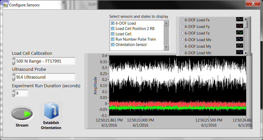
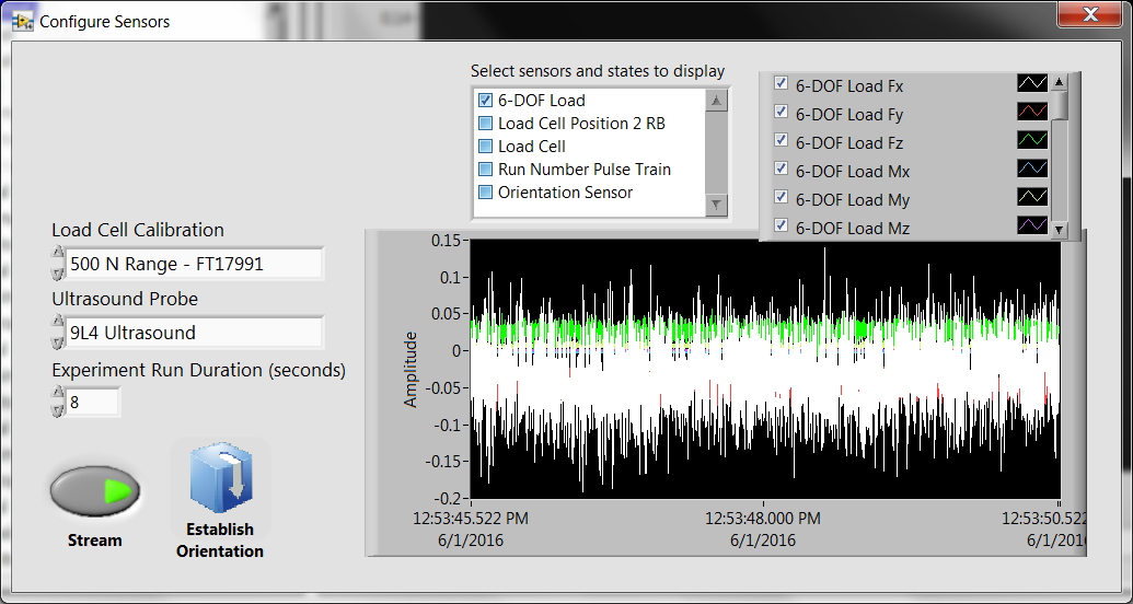
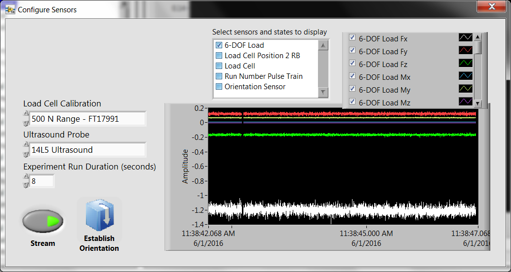
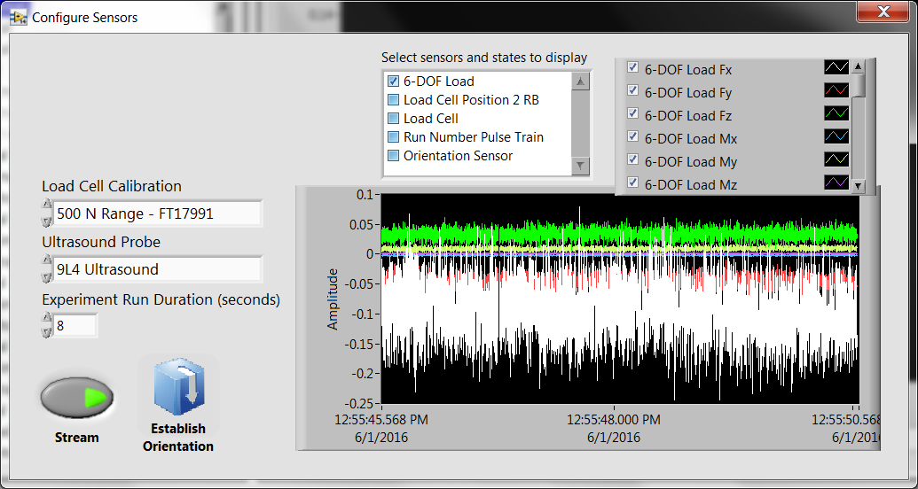
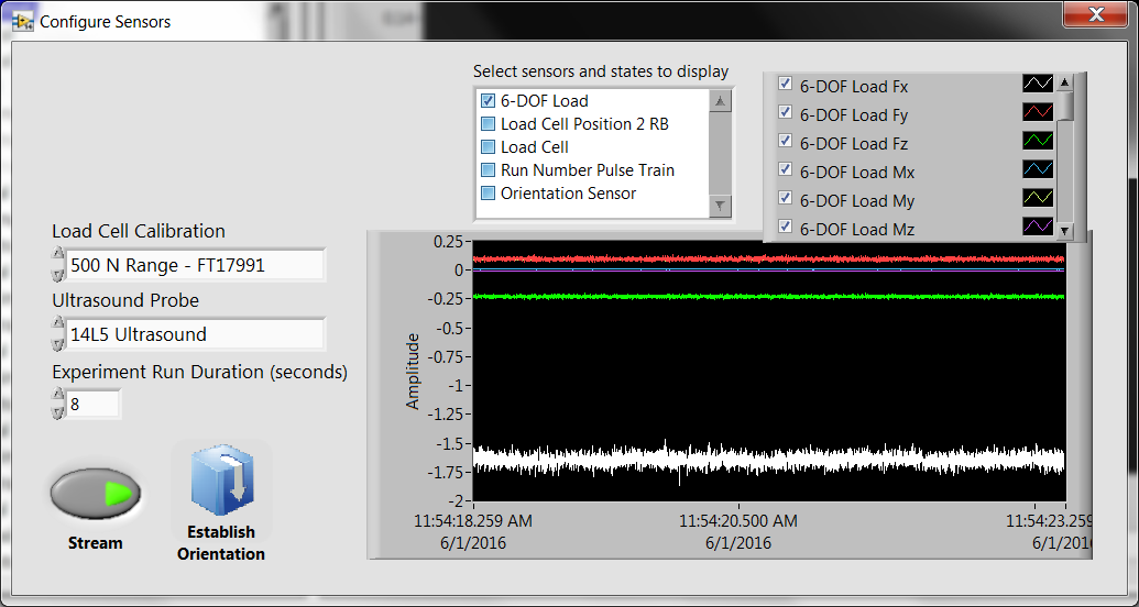
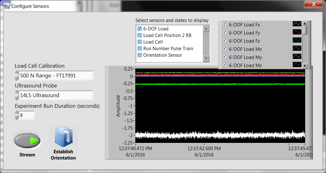
*Considerable drifting in Load Fx after several hours.
|
Test 1 |
|
Test 2 |
10:10 |
Load cell turn on |
|
Load cell kept on |
11:17 |
|
12:50 |
|
11:22 |
|
12:53 |
|
11:38 |
|
12:55 |
|
11:54 |
|
|
|
12:37 |
|
|
Considerations after mock-up testing - Session VI
Ahmet & Tyler review all data files generated during data collection
- XML, TDMS, state, sensor files
- Tammy: If force collection is rejected and no ultrasound was collected, make a note under notes section
- Tara/Robb: What does the offset matrix do in the state configuration file?
- Go over sensor/state file with Tara/Robb to understand every line
What does ">0<" indicate in XML e.g. Male>0<
- Tara: Activity level does not hold (similar problem to when leg circ. data flipped)
- TDMS file:
- add lines to indicate sensor, probe used
- add static transformation matrix and all other matrices
- use more descriptive names within file
- what is load cell position 2 RB
- DICOM:
- the pulse train is read by the ultrasound as an EKG signal and has the ability to measure peak-to-peak times as it would for a typical QRS complex
- Recorded as an R-wave time vector in metadata of the DICOM
"The time offset(s) of the reported R Wave peaks, each relative to the time of the start of the acquisition of the first frame in msec. Multi-valued, with one value per reported R Wave." -http://neurolex.org/wiki/Category:R_Wave_Time_Vector
- We hypothesize that a signal encoded via specific time intervals can be used as the pulse-train and extracted via metadata easily, thus making it easy to identify start.
- For subject ID and trial run, encode various time intervals.
Considerations after mock-up testing - Session VII
- Conducted a complete session to test the software.
- During the initial configuration, all channels were displayed.
- If the system needs to be restarted, the software allows the user to choose the subject number to continue testing. Currently, this defaults to MULTIS001. Since we will most likely be retesting the most recent subject, could this default to the "highest" subject number?
- Config (i.e. height, weight) not always saving.
- During all data collections, the side of the ultrasound probe with the vertical mark should always be directed superiorly on the subject. Thus, the probe will be "flipped" during posterior testing.
- At the end of the data collection, once all trials have been completed, could there be an indicator on the screen stating that all trials have been completed.
- During lower leg testing, all trials will be directed toward the fibula except for the posterior trials which will be directed toward the tibia.
- During lower arm testing, all trials will be directed toward the radius except for the medial trials which will be directed toward the ulna.

Settings
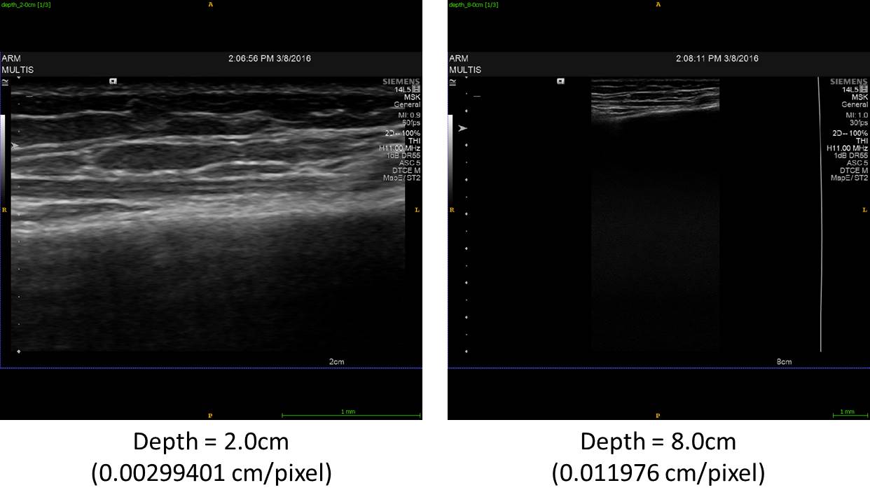
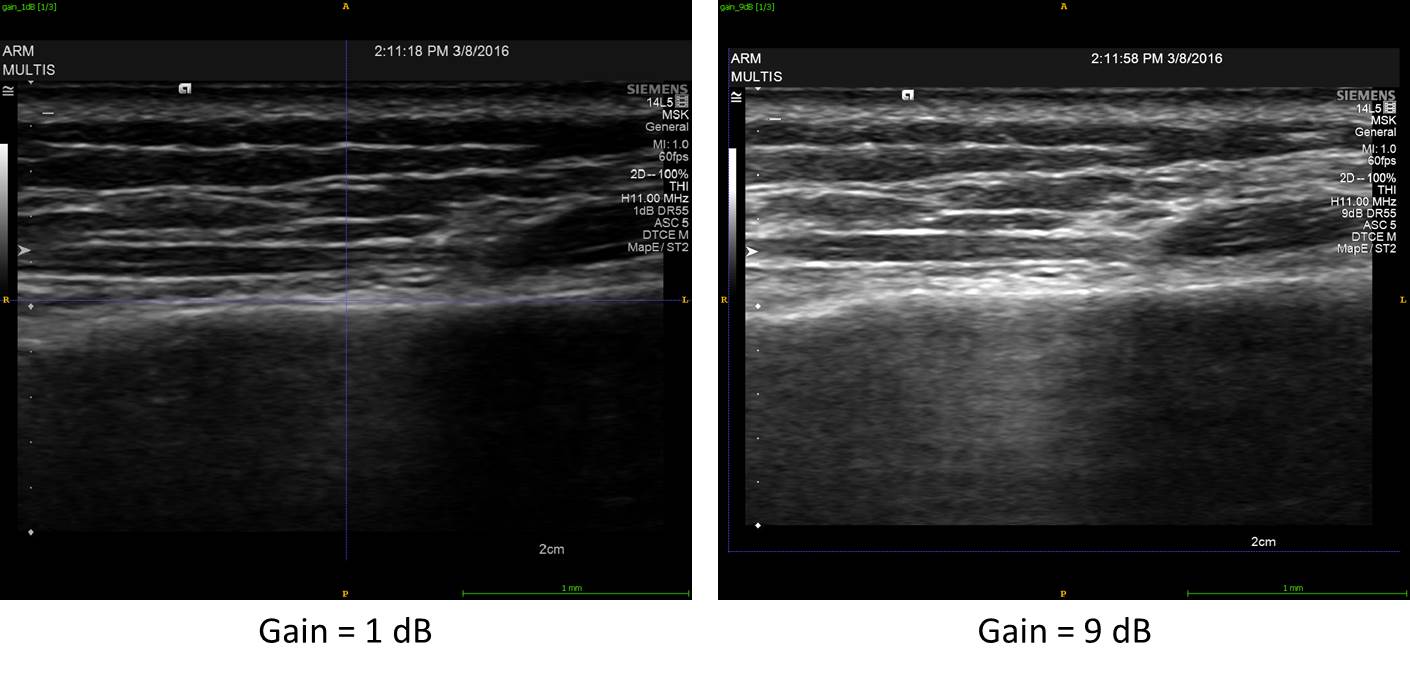
Gain: The overall brightness of the image can be adjusted. This can also be adjusted during post-processing. There is no change in resolution. We plan to use the TEQ button to optimize the gain.
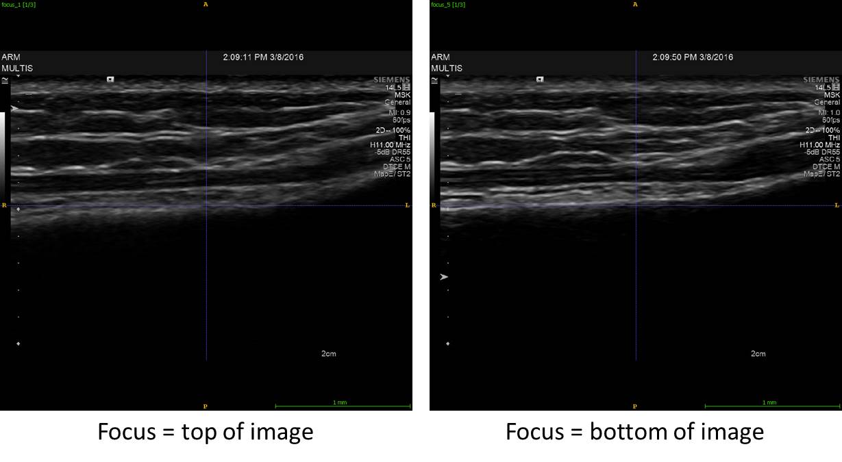
Focus: The pulse of the ultrasound can be manipulated to be at its narrowest at a particular depth so the region can be examined in more detail. There is no change in resolution. We plan to adjust the focus so that it is in the middle of the region of interest (skin to bone).
Depth: Increasing the depth allows deeper structures to be viewed, but reduces the scale. Increasing the resolution along the depth will decrease the field of view along the width. We have chosen to fill the screen with the entire image.
